50
4. Car Music Storage Unit
IC501
SYSTEM
CONTROLLER
IC4001
DSP
MAGIC
GATE
TM
MEMORY
STICK®
21
CLK
S CLK 8
N/C 7
INS 6
N/C 5
D IO 4
3.3V 3
BS 2
GND. 1
VCC 9
GND. 10
SW. 11
SW. 12
24
D4206
22
IC1010
CPU
Q4201,
Q4202
20
3630
31
21
23
D4205
DET 1
SWITCH
SW.3.3V
SERIAL DATA
MISC.
SW.
INPUTS
IC2003,
IC4301
SUB BD.
MAIN BD.
MEMORY
STICK®
D 3.3V
CN5002/
CN526
XCS5
XRST
XRD
XWE
ADDRESS & DATA BUS
DET 0
10-PIN
MEMORY
STICK®
SOCKET
(TOP)
CN526/CN3002
LOCK
PINS 1,6,10 ARE
CONNECTED
MEMORY
STICK®
BOTTOM
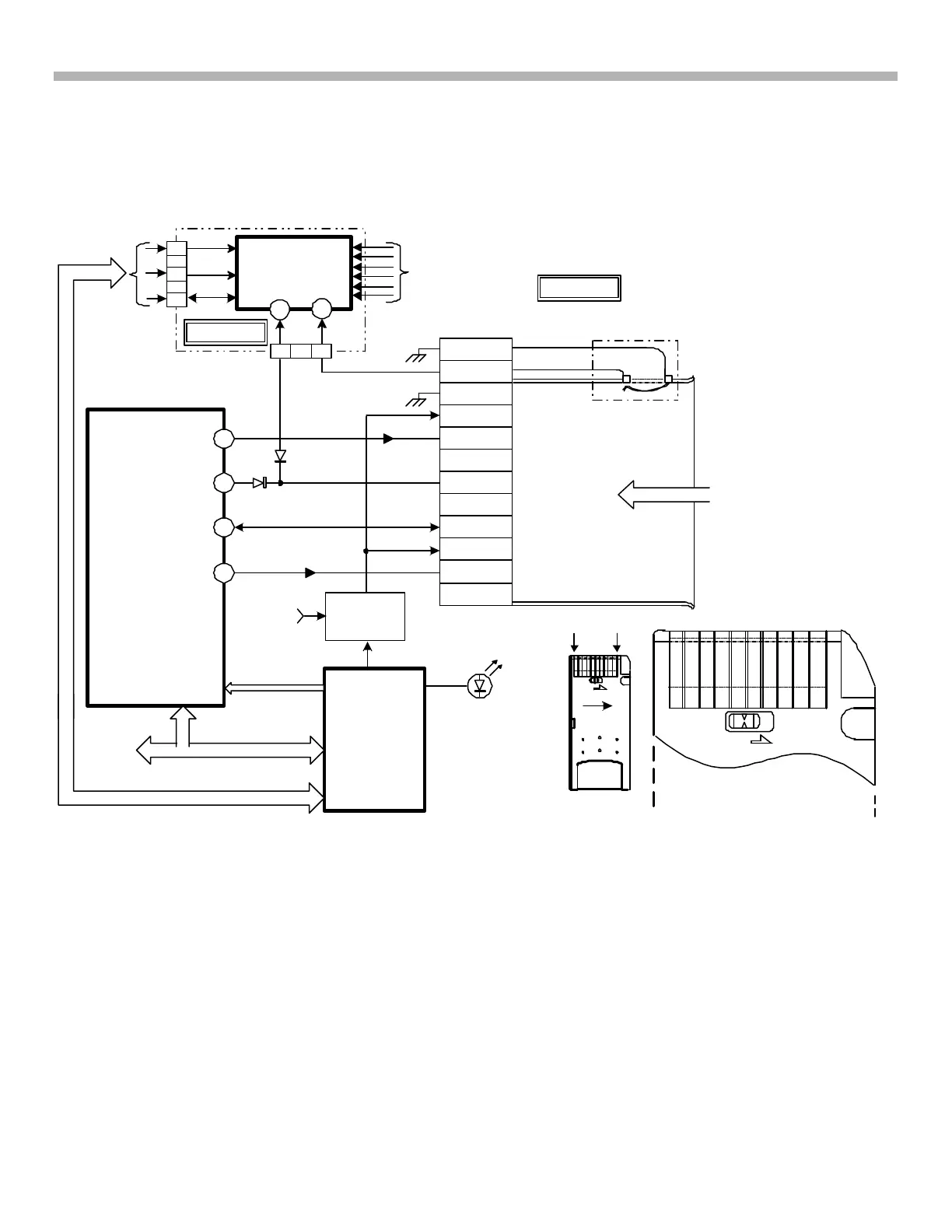
FIGURE 4-15 - MEMORY STICK® CIRCUIT
MEMORY
STICK®
PINS 10
1
WDT
RXD
TXD
10
1
LOCK
34 33
4-5A125 1516 11/19/02
Memory Stick® Circuitry
Refer to Figure 4-15. The Memory Stick® is ¾ the length of a piece of chewing gum at double the thickness. It
contains ICs that store data. The capacities available are listed in the appendix of this book. Only the white
plastic colored Magic Gate
TM
(MG) Memory Sticks® can be used in this MEX-1HD to check out and music back
into the hard drive. While the stick has the music, it can be played in a Network Walkman® or other devices.
Physically the stick itself has ten gold pins on the bottom with a manual data lock switch to prevent recording,
changing or deleting the data. The socket has 12 pins. The two extra pins (11 and 12) are connected to a socket
switch to detect the stick insertion. Pin 6 is grounded by the Memory Stick® when inserted as well.
When IC4001 detects the Memory Stick® presence, its contents are read. IC501 confirms the presence of the
stick and informs CPU IC1010 to get ready for data and enable the Memory Stick® LED to light when data is
transferred (PB or read).
The Memory Stick® data to produce audio is output pin 8, is uncompressed by DSP IC4001 and output as digital
audio. See Figure 4-14 for the remainder of the audio path where the next step is digital to analog conversion by
IC371 (main board).



 To Next Page