5
1. Car Power Amplifier
IC101-IC104
PREAMP./FILTER
L
IC201-IC204
PREAMP./FILTER
R
Q103-Q113
OUTPUT STAGE
L
Q203-Q213
OUTPUT STAGE
R
R229
R801 1M
20V
+
-
L
R
R129
1
2
3
4
Q102
Q202
Q102,Q202 LINE SW.
LEFT
OUTPUT
RIGHT
OUTPUT
20V
14.2V
R804
100k
R805
D802
D801
6.8V
Q802
Q801
R802
IC902
SWITCHED
+12V
TO DC-DC
CONV. IC901
IC902
GROUND
ISOLATION
-14.2V
+12V
BATTERY
REM
C913
0.001
R909
R928
100k
R911
100k
POWER
ON
(7.4V MIN.)
D902
17V
R912
Q902
P
P
Q901
F901
40A
R907
R908
D901
8.8V
R906
4.7k
Q903
N
0V
C801
22
+
P
20V
N
N
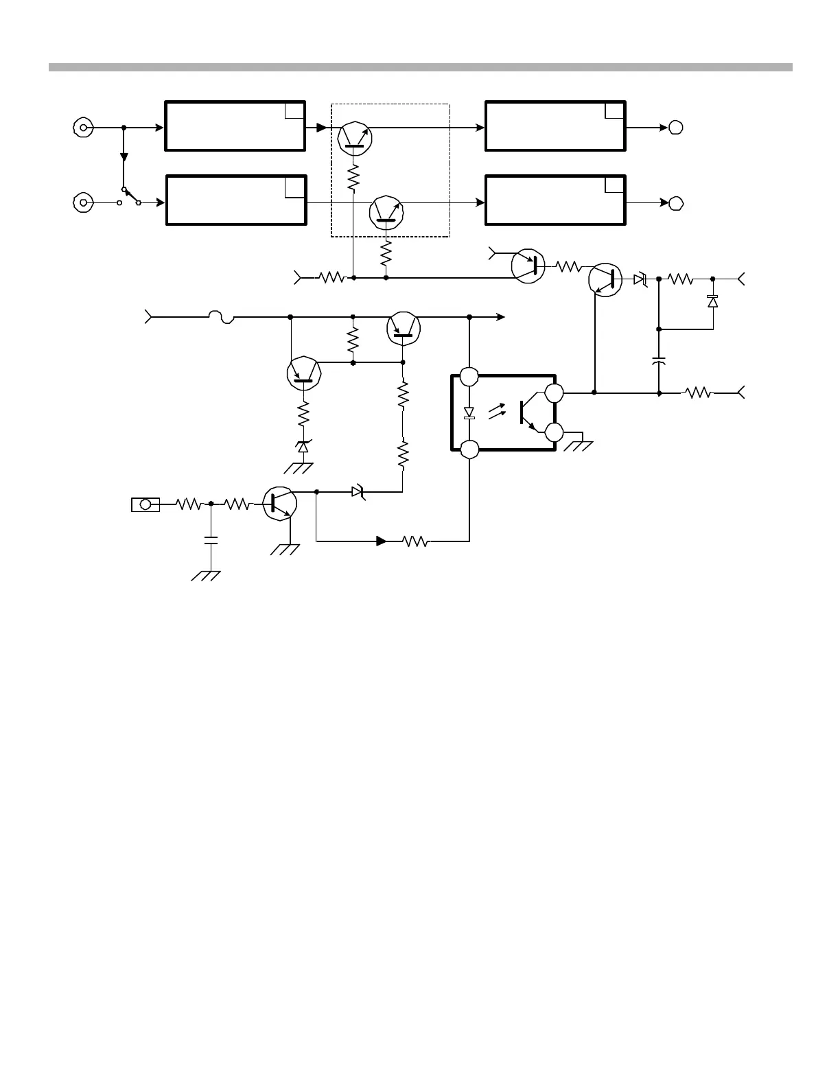
FIGURE 1-3 - POWER ON/AUDIO UNMUTE
N
11A125 1486 11/4/02
0V
9V
UNMUTE
Power ON
Refer to Figure 1-3. Power ON occurs when Battery +12Vdc passes through Q901 to the DC-DC Converter.
Q901 is turned on by Q903 that is turned on when at least 7.4Vdc is input the REM terminal. The 7.4Vdc
minimum turn ON threshold is set using an 8.8V zener D901 at Q903/collector. When Q903 conducts almost
fully (requiring 7.4V input), then zener D901 conducts. Current flows from Q901/emitter – base, through D901
and Q903 to ground. When Q901 conducts, Battery +12V is applied to the DC-DC Converter.
Power ON Inhibit
Power ON is inhibited if the Battery +12Vdc rises to 17.6Vdc or above. Zener D902 and Q902 keep Q901 off
when the input voltage is excessive. If the car alternator output rises to 17.6V or above, current flows from the
40A fuse through Q902/emitter – base, R912 and D902 to ground, turning ON Q902. When Q902 conducts,
Q901/emitter to base is shorted (bypassed) so Q901 cannot conduct to turn ON the amplifier.
Audio Un-Mute
Refer to Figure 1-3. Audio is un-muted at power ON. When Q903 turns ON to power ON the amplifier, it also
turns on IC902 to start the un-mute process. When IC902/pin 3 goes LOW, both Q801 and Q802 conduct
bringing +20Vdc (at Q801/pin collector) into the two line switching transistors Q102 and Q202. The higher
voltages at both bases permits them to conduct and both line switching transistors pass the audio signal from
collector to emitter (same signal level at both terminals).



 To Next Page