6
1. Car Power Amplifier
1
2
Q903
POWER
ON/OFF
Q901, 902
B+
SWITCH
IC902
DC
DET.
Q813
LED
DRIVE
Q812 PROT.
LATCH
Q809
LED
INHIBIT
Q811
LED
DRIVE
Q810
PROT.
LATCH
12
3
1
2
15
16
14
REF.
REG.
10
11
9
8
Q904/5
Q906/7
D808
D811
POWER
THERMAL
THP802-3,
TH801-813
TEMP. DET.
D810
OFFSET
D809
OVER CURRENT
REM
12V
GND
Q808
IC901
DC-DC
CONVERTER
TO Q801,802
FROM
OFFSET
DETECT
CIRCUIT
FROM
OVER
CURRENT
CIRCUIT
F901
D807
D803
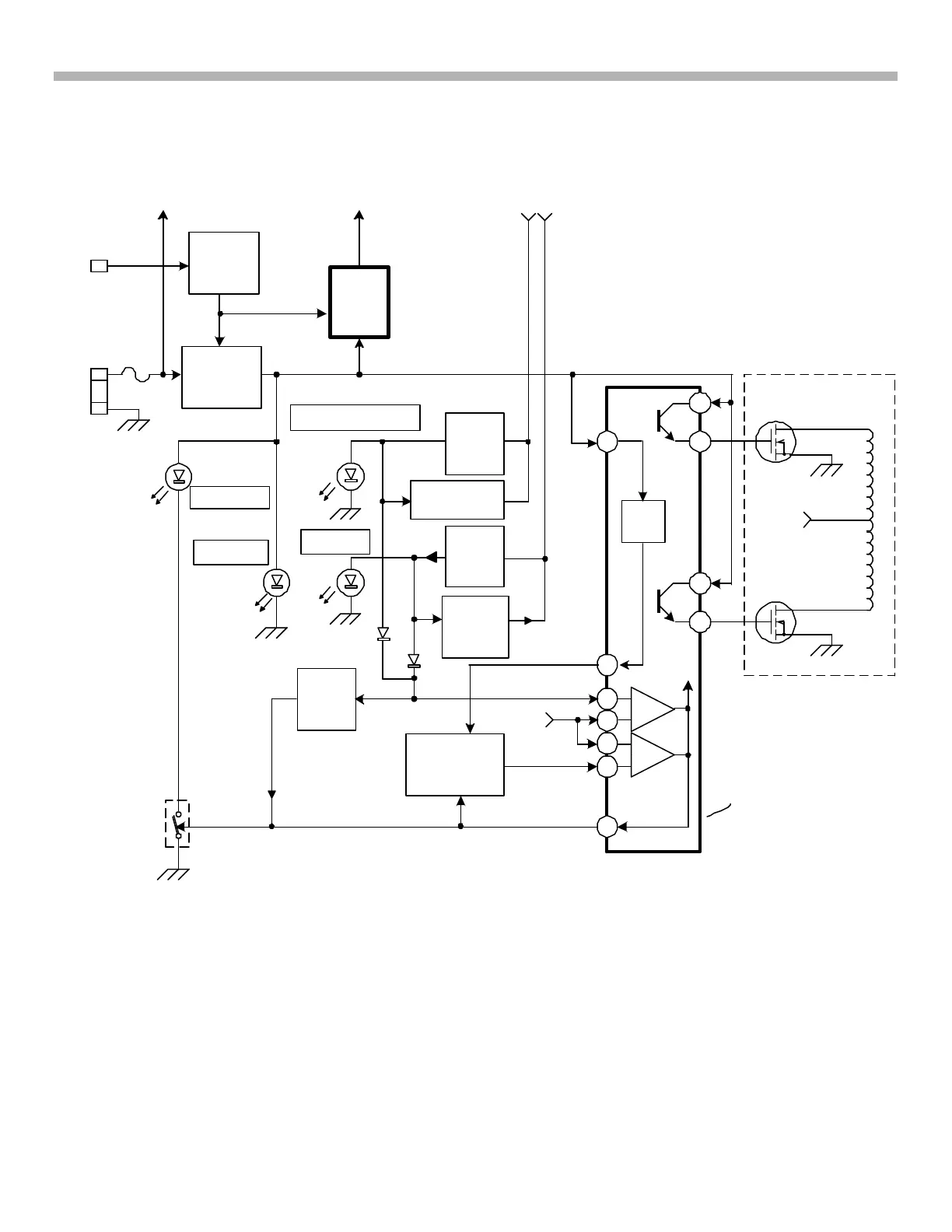
FIGURE 1-4 - POWER SUPPLY
TO T901
T901
+12V
FROM
F901
1.2V
REF.
TEMP
LATCH
SW.+12V
0.2V
0V
OSC.
STOP
STOP
5.0V
1
1A125 11/12/02
OSC.
START
Pulse Power Supply – Oscillator / Output
Refer to Figure 1-4 (oscillator) and 1-5 (driver). The switching power supply consists of the oscillator within
IC901, the MOSFET drivers (Q904-8) transistors and the multiple winding transformer (T901) that it feeds.
Circuit Operation
IC901’s internal oscillator starts and produces a 36kHz output at pins 9 and 10 when four conditions are met:
1. Vcc is applied to IC901/pins 8, 11 and 12 of at least 5.9Vdc (normally = battery voltage).
2. Protection Latch 1 and 2 applied to IC901/pin 1 is less than 1.2Vdc.
3. Thermal Sensing voltage applied to IC901/pin 16 is less than 1.2Vdc.
4. Feedback for regulation at IC901/pin 4 (not shown) is less than 3Vdc.



 To Next Page