7
1. Car Power Amplifier
R930
R931
Q908
0.7V
0.3V
Q909
0.3V
0.7V
R918
R942
R913
R914
R932
R933
R919
R915
R917
R943
R922
R920
C942 C919 C918 C917
*ALL
CAPACITORS
2200 18V
TO
REGULATION
0.6V
14.6V
Q906
0.6V
Q907
FROM
IC901
PIN 9
FROM
IC901
PIN 10
R916
0.7V
Q904
0.7V
14.6V
14.6V
R921
Q905
B+
T901
DC-DC
CONVERTER
TRANSFORMER
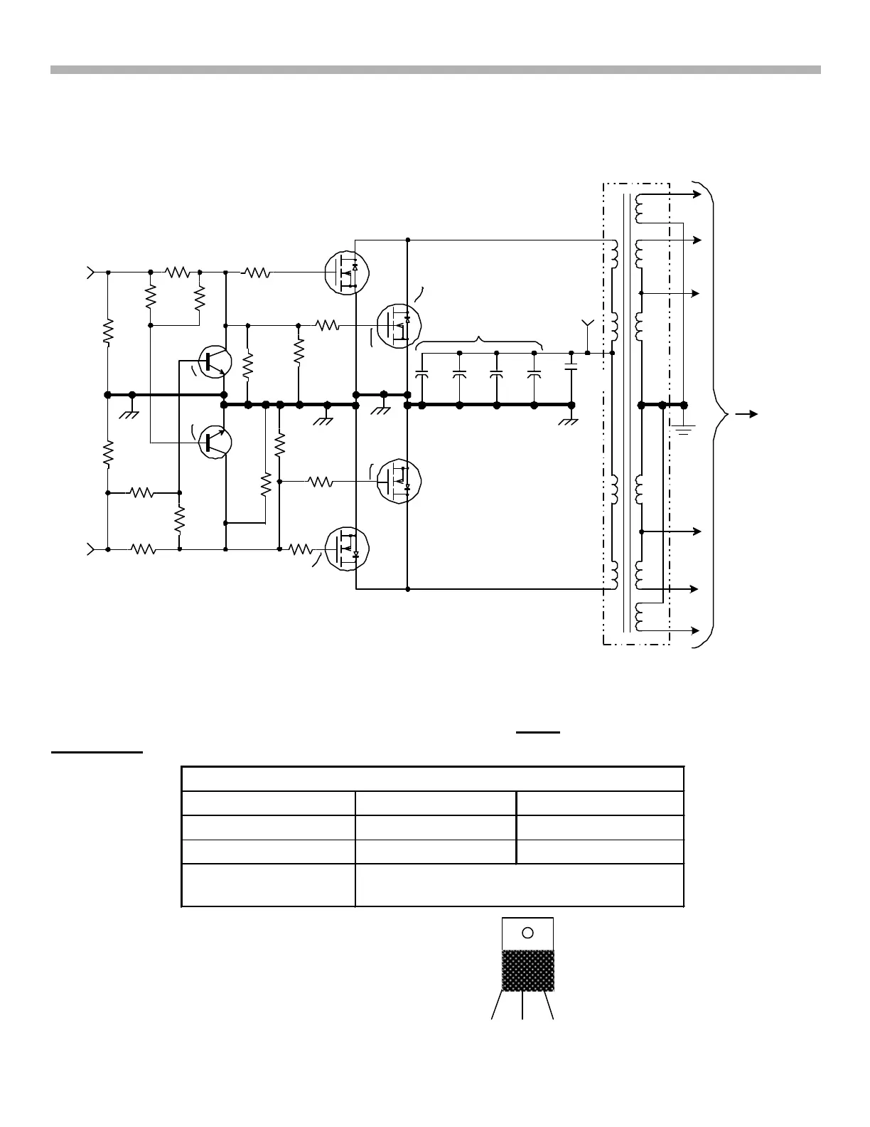
FIG.1-5 POWER SUPPLY PRIMARY
0.3V
+
+ + +
* NOTE CAPACITOR
VALUES
C916
5A125 1458 11/11/02
14.6V
Referring to Figure 1-5, the oscillator signal is output and amplified by Q904 - Q907, which are four MOSFET
devices that feed T901. Q908 and Q909 are spike overload prevention transistors that prevent Q904/5 from
conducting at the same time Q906/7 are conducting and vice versa. For example, when a positive signal is
output IC901/pin 10, the positive drivers Q904/ Q905 turn ON. Prevention transistor Q909 also turns ON and in
doing so grounds any turn on signal to the negative drivers, Q906 and Q907 because only one set of drivers
should be ON, not both.
Pulse Power Supply – Testing
The MOSFETs can be tested with an ohmmeter. There is a static test for shorts (Table 1-2) and an
operational test for functionality.
Table 1-2 - Static MOSFET Resistance Tests
Apply DVM Probes at: + / - - / +
Gate – Source Infinity Infinity
Gate - Drain Infinity Infinity
Drain - Source There is a zener diode connected internally
across these terminals
Power MOSFET
P or N channel
TO-220 case
D
G D S



 To Next Page