44
4. Car Music Storage Unit
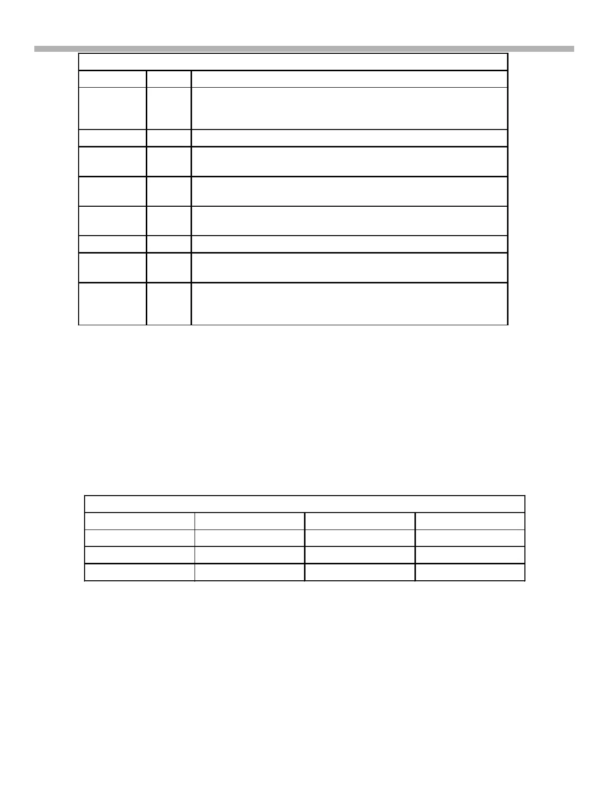
Table 4-7 - CD Circuit Control
IC Board Function
IC1 Servo Amplifies the RF data, focus and tracking signal from the
Optical assembly for IC8. Regulates the laser light intensity
after being turned ON by IC8.
IC5, IC6 Servo Spindle, Sled, focus and tracking coil current amplifier
IC8 Servo Main CD controller, outputting processed digital audio through
IC2003 to DSP IC4001 for audio output.
IC9 (not
shown)
Servo Flash Memory supports IC8 for start up disc check, ID and
playback of different CD-R and CD-RW discs.
IC2003 Servo Translates the digital data between the two data bus to relay
the digital audio form IC8 to IC4001.
IC4001 Main Digital Signal Process (DSP). Outputs Digital Audio to IC371.
IC1010 Main Main CPU turns on CD operation and learns if there is a disc
present.
IC371,
IC301 (not
shown)
Main Dig to Analog Converter and Electric volume controller for
audio output processing. IC371 and IC301 not shown.
CD board Access
The following pictures will help you access the CD parts:
Figure 4-9 - Ribbon connectors are either slide or lift types to release.
Figure 4-10 - Remove the top tray gives you access to the CD servo board.
Figure 4-11 - Lifting and flipping the servo board shows the driver ICs.
Figure 4-12 - Signal and power input can be checked using a small disc even if it does not contain audio. Pin 1
is marked on the board.
Table 4-8 - CN 6 Power Input Voltages
CN6/Pin Voltage / label CN6/Pin Voltage / label
3 and 4 S5V 8 D3.3V
5 A5V 9 Ground
7 A3.3V 10 D5V



 To Next Page