MEX-BT4100E/BT4100P/BT4100U/BT4150U
6
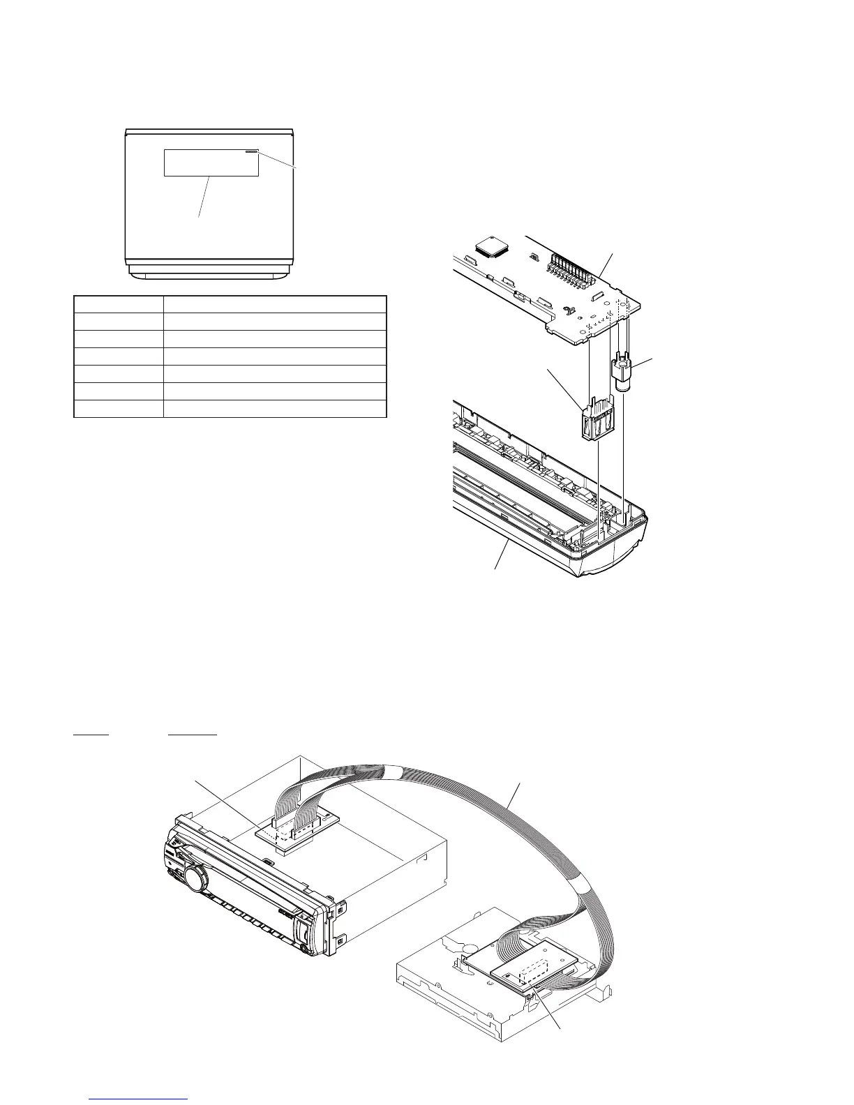
EXTENSION CABLE AND SERVICE POSITION
When repairing or servicing this unit, connect the jig cable (extension cable (CD mecha)) as shown below.
• Connect the MAIN board (CN700) and the SERVO board (CN401) with the jig cable.
Jig cable:
Part No. Description
A-1818-424-A EXTENSION CABLE (CD MECHA)
SERVO board
(CN401)
MAIN board
(CN700)
extension cable (CD mecha)
MODEL IDENTIFICATION
– Bottom View –
Part No.
Model Number Label
Part No. Destination
4-436-200-0[]
BT4100U: AEP and UK models
4-436-201-0[]
BT4100P: US and Canadian models
4-436-202-0[]
BT4100E: Russian model
4-436-203-0[]
BT4150U: E model
4-436-204-0[]
BT4150U: Mexican model
4-436-205-0[]
BT4150U: Saudi Arabia model
NOTE FOR REPLACEMENT OF THE USB CONNEC-
TOR (CN971) AND THE AUX JACK (J901)
To replace the USB connector and AUX jack requires alignment.
1. Insert the USB connector and AUX jack into the front panel.
2. Place the KEY board on the front panel and align the terminals
of the USB connector and AUX jack with the holes in the KEY
board.
3. Solder seven terminals of the connector and three terminals of
the jack.
KEY board
front panel
USB (socket) connector
(CN971)
AUX jack
(J901)
Ver. 1.1