Chapter 2 Location and Function of Parts
Chapter 2 Location and Function of Parts 2-19
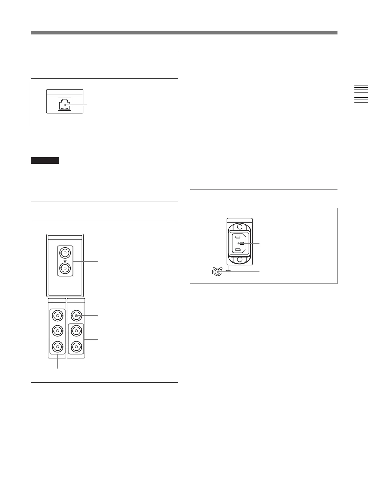
4 Network connection section (MSW-
M2000E/M2000EP only)
Ethenet connector
Connect to a network by 10/100/1000Base-T.
CAUTION
For safety, do not connect the connector for peripheral
device wiring that might have excessive voltage to this
port. Follow the instructions for this port.
5 Digital signal input/output section
1 SDI (Serial Digital Interface) INPUT connectors
(BNC type)
Input D1 format digital video/audio signals. Of the two
connectors, the upper one is for input, and the lower
one is for an active-through connection.
2 SDTI-CP (Serial Data Transport Interface)
INPUT connector (BNC type)
Inputs SDTI-CP format video and audio signals.
3 SDTI-CP (Serial Data Transport Interface)
OUTPUT connectors (BNC type)
Output SDTI-CP format video and audio signals.
4 SDI (Serial Digital Interface) OUTPUT
connectors (BNC type)
These connectors output D1 format digital video/audio
signals.
When the setting of F4 (CHARA) in function menu
page 4 is ON, connector 3 (SUPER) outputs a signal
with superimposed time code, menu settings, alarm
messages, and other text information.
6 Power supply section
1 AC IN connector
Use the optional power cord to connect this to an AC
outlet.
2 Ground terminal
Connect this to ground.
1 AC IN connector
2 Ground terminal
1 SDI INPUT connectors
2 SDTI-CP INPUT connector
3 SDTI-CP OUTPUT connectors
SDI
SDI
INPUT
OUTPUT
OUTPUT
1
2
3(
SUPER
)
SDTI-CP
INPUT
1
2
Ethernet connector
Ethernet
4 SDI OUTPUT connectors