1-8
MVS-8000X/7000X
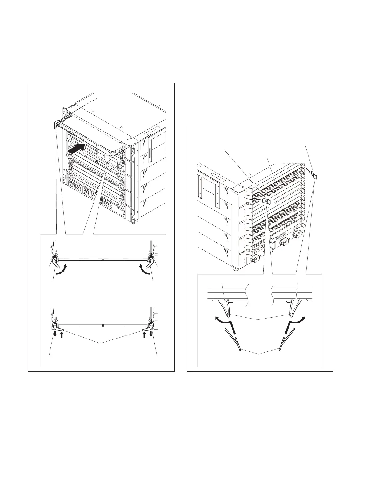
5. Close the both eject levers at a time, when the eject
lever claws reach the A position (1).
And push the eject levers (2) until the unlock buttons
pop out.
A
11
2
3
3
2
A
Eject lever Eject lever
Eject lever
Unlock button Unlock button
This figure shows MVS-8000X
1-4-2. Installing the Connector Board
Service Tool
Lever unlock jig : Part No. 4-193-124-01
1. Insert the protrusion of the lever unlock jigs into the
red groove of the blank panel's rear levers (1) and
while pushing the lever unlock jigs, open the rear
levers outward to unlock.
1 1
Unlock button
Lever unlock jig
Lever unlock jig
Rear leverRear lever
Lever unlock jig
Blank panel
This figure shows MVS-8000X

 Loading...


