1-11
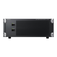
MVS-8000X/7000X
1-5. Rack Mounting
The MVS-8000X/MVS-7000X is mounted in the 19-inch
standard rack.
Precautions for Rack Mounting
w
. To prevent the rack from falling or moving, fi x the rack
on a fl at and steady fl oor and the like using bolts or
others. If the rack falls due to the weight of the equip-
ment, it may cause death or serious injury.
. Be sure to use the rack mount parts (supplied with MVS-
8000X). If not, injury may result and the equipment may
fall due to insuffi cient strength.
. After rack mounting, be sure to tighten the screws on the
rack angle and fi x the unit in the rack. If the screws on
the rack angle are not tightened, the unit may slip from
the rack and fall, causing injury.
w
When mounting the unit in the rack, note the following:
. Be sure to mount in the rack with two persons or more.
. Be careful not to catch your fi ngers or hands in the rack
mount rail or others.
. Hold the bottom of unit and mount in the rack in a stable
position.
w
If several units are mounted in a rack, it is recommended to
install a ventilation fan to prevent temperature rise inside
the rack.
1-5-1. MVS-8000X
To mount the MVS-8000X in the rack, use the rack mount
parts (supplied with MVS-8000X) and follow the proce-
dure described below.
n
If other than the rack mount parts (supplied with MVS-
8000X) is used, the unit may not be mounted in the 19-inch
standard rack.
Using parts list (Accessory of the MVS-8000X)
. Rack tool 2pcs
. Support angle 2pcs
. Bracket 4pcs
. Rack tool attaching screw
(+B4 x 6 : 7-682-560-04) 6pcs
. Support angle attaching screw
(+PSW4 x 10 : 7-682-962-01) 8pcs
. Bracket attaching screw
(+B4 x 10 : 7-682-562-04) 8pcs
Other required parts
. Screw for rack mounting
(+B5 x 12 : 7-682-576-09) 4pcs
Rack Mounting Procedure
1. Loosen the four screws (+B4 x 8) and remove the four
feet.
+B4 s8
+B4 s8
Feet
Feet
2. Remove the front panel of the equipment.
(Refer to Section 1-4-1.)
3. Attach the rack tool to the side of the equipment using
the specifi ed six screws.
n
Use +B4 x 6 screws. Tighten the screws to the follow-
ing torque.
Tightening torque : 120 x 10
_2
N.m {12.2 kgf . cm}
+B4 s6
+B4 s6
Rack tool
Rack tool

 Loading...


