Do you have a question about the Sony MZ-RH10 and is the answer not in the manual?
Step-by-step guide for component disassembly.
Procedure for removing the lower case assembly.
Procedure for removing the main board assembly.
Procedure for removing the upper panel section.
Procedure for removing the mechanism deck.
Procedure for removing the battery case block.
Procedure for removing gears.
Procedure for removing the optical pick-up service assembly.
Procedure for removing DC motors and unit.
Procedure for removing the holder assembly.
Instructions on ferrite core placement on cables.
General description of test mode operation and LCD displays.
Steps to enter and operate the test mode.
Flow and configuration of different test modes.
Procedure to reset adjustment values to default.
Procedure for adjusting power supply voltages.
Procedure to check the battery charging function.
Procedure to measure and adjust laser power.
Procedure for setting various adjustment values.
Procedure for overall servo adjustment.
Procedure to clear adjustment data.
Procedure to exit the test mode safely.
Block diagram of the MD servo system.
Block diagram of the audio processing section.
Block diagram of the power supply system.
Schematic of the main board (part 1).
Schematic of the main board (part 2).
Schematic of the main board (part 3).
Schematic of the main board (part 4).
Schematic of the main board (part 5).
Schematic of the main board (part 6).
Schematic of the main board (part 7).
Schematic of the main board (part 8).
Schematic of the main board (part 9).
Component layout on the main board (component side).
Component layout on the main board (conductor side).
Exploded view of the lower case section.
Exploded view of the upper panel section.
Exploded view of the chassis section.
Exploded view of the mechanism deck.
| Brand | Sony |
|---|---|
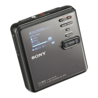
| Model | MZ-RH10 |
| Category | MiniDisc Player |
| Language | English |