EasyManua.ls Logo

Sony MZ-E10 Service Manual

Sony MZ-E10
40 pages
To Next Page IconTo Next Page
Page #1 background imageLoading...
Page #1 background image
Battery life
1)
(Unit: Approx. hours) (JEITA
2)
)
Batteries SP Stereo LP2 LP4
(normal) Stereo Stereo
Lithium-ion 23 33 40
built-in
rechargeable
battery
3)
1)
Measured with the power save function on (see
“ Preserving battery power” ).
2)
Measured in accordance with the JEITA (Japan Electronics and
Information Technology Industries Association) standard (using a Sony
MDW-series Mini-disc).
3)
With a fully charged battery.
Note
The battery life may be shorter than that specified, depending on the
operating conditions,the temperature of the location.
Dimensions
Approx. 81.9 x 72.2 x 9.9 mm (w/h/d) ( 3
1
/
4
x 2
7
/
8
x
13
/
32
in.)
(not including projecting parts and controls)
Mass
Approx. 55 g (1.6 oz) (including the built-in rechargeable battery)
Supplied accessories
Headphones/earphones with a remote control (1)
Battery charging stand (1)
AC power adaptor (for the supplied battery charging stand) (1)
Headphone adaptor (1)
Carrying pouch (1)
Design and specifications are subject to change without notice.
MZ-E10
SERVICE MANUAL
PORTABLE MINIDISC PLAYER
SPECIFICATIONS
US Model
Canadian Model
AEP Model
UK Model
E Model
Tourist Model
Model Name Using Similar Mechanism NEW
MD Mechanism Type MT-MZE10-184
Optical Pick-up Mechanism Type ABX-1ES
US and foreign patents licensed from Dolby
Laboratories Licensing Corporation
Ver 1.0 2002.11
9-874-219-01
2002K0200-1
© 2002.11
Sony Corporation
Personal Audio Company
Published by Sony Engineering Corporation
Audio playing system
MiniDisc digital audio system
Laser diode properties
Material: GaAlAs
Wavelength: λ = 790 nm
Emission duration: continuous
Laser output: less than 44.6 µW*
* This output is the value measured at a distance of 200 mm from the
objective lens surface on the optical pick-up block with 7 mm aperture.
Revolutions
Approx. 300 rpm to 2,700 rpm
Error correction
ACIRC (Advanced Cross Interleave Reed Solomon Code)
Sampling frequency
44.1 kHz
Coding
ATRAC (Adaptive TRansform Acoustic Coding)
ATRAC3: LP2/LP4
Modulation system
EFM (Eight to Fourteen Modulation)
Number of channels
2 stereo channels
1 monaural channel
Frequency response
20 to 20,000 Hz ± 3 dB
Outputs
Headphones/earphones: dedicated headphone/ remote control jack,
output level 5 mW + 5 mW(US model) load impedance 16 ohms,
5 mW + 5 mW (Other models)
load impedance 16 ohms
Power requirements
Lithium-ion rechargeable battery (Built-in: LIP- 3WMB, 3.7 V,
340 mAh, Li-ion)
External power jack (for the battery charging stand): Power rating 6 V
DC

Other manuals for Sony MZ-E10

Question and Answer IconNeed help?

Do you have a question about the Sony MZ-E10 and is the answer not in the manual?

Sony MZ-E10 Specifications

General IconGeneral
TypeMiniDisc Player
Release Year2000
Sampling Rate ConverterYes
Digital InputNo
Headphone OutputYes
Frequency Response20 Hz - 20 kHz
Signal-to-Noise Ratio90 dB
Remote ControlYes
Power SourceAA battery
Supported FormatsATRAC
OutputHeadphones

Summary

Specifications

Audio System Details

MiniDisc playback, laser properties, and error correction.

Performance Specifications

Revolutions, sampling frequency, coding, and frequency response.

Power and Physical Details

Power requirements, battery life, dimensions, and mass.

Included Accessories

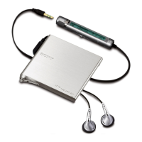
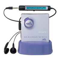
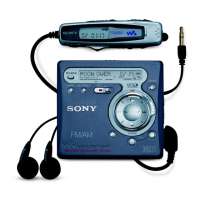
List of accessories provided with the player.

Safety and Precautions

Flexible Circuit Board Repairing

Guidelines for repairing flexible circuit boards safely.

Chip Component Replacement Notes

Precautions for replacing chip components.

Safety-Related Component Warning

Warning for critical safety components.

Servicing Notes

General Information

Playing an MD

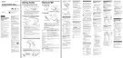
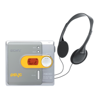
Instructions for inserting and playing MiniDiscs.

3-Color Info-LED Indicators

Explanation of the 3-color LED indicators and their meanings.

Disassembly Procedures

Panel Assembly Disassembly

Procedure for disassembling the upper panel assembly.

Mechanism Deck Removal

Procedure for removing the mechanism deck.

Bracket Assembly Disassembly

Procedure for disassembling the bracket assembly.

Power and Main Board Removal

Procedure for removing the power and main boards.

Control Board Disassembly

Procedure for disassembling the control board.

Optical Pick-up Assembly Disassembly

Procedure for disassembling the optical pick-up assembly.

Test Mode Operations

Test Mode Overview

Overview of the Test Mode and its adjustment capabilities.

Setting the Test Mode

Methods for entering the Test Mode.

Test Mode Operations

Operations and displays within the Test Mode.

Test Mode Structure

Diagram showing the structure and flow of Test Mode options.

Manual Mode Adjustments

Detailed procedure for manual adjustments and checks.

Overall Adjustment Mode

Mode for automatic servo system adjustment.

Key Check Mode

Procedure for checking the functionality of all keys.

Electrical Adjustments

Adjustment General Information

General information on automatic adjustments within Test Mode.

Adjustment Notes and Preparation

Notes on jigs, sequence, and power for adjustments.

NV Initialize Procedure

Procedure to clear non-volatile memory.

Changing Adjustment Values

Methods for changing adjustment values.

Adjustment Value Change Method 1

Step-by-step guide for changing adjustment values (Method 1).

Power Supply Voltage Adjustments

Procedures for adjusting power supply voltages.

Charge Adjustments

Procedures for adjusting charging circuits.

Temperature Adjustment

Method for adjusting temperature compensation.

Overall Adjustment Mode Structure

Structure and operation of the Overall Adjustment Mode.

Resume Clear Method

Method for clearing resume data after battery replacement.

Rewriting Patch Data

Procedure for rewriting patch data after replacing non-volatile memory.

Diagrams

Block Diagrams

Block diagrams illustrating the system architecture.

Printed Wiring Boards - Main Section (1/2)

Printed wiring board layout for the main section (part 1).

Printed Wiring Boards - Main Section (2/2)

Printed wiring board layout for the main section (part 2).

Schematic Diagram - Main Section (1/3)

Schematic diagram for the main section (part 1).

Schematic Diagram - Main Section (2/3)

Schematic diagram for the main section (part 2).

Schematic Diagram - Main Section (3/3)

Schematic diagram for the main section (part 3).

Waveforms

Illustrations of key signal waveforms and their characteristics.

IC Pin Function Description

Detailed pin functions for major integrated circuits.

IC Block Diagrams

Block diagrams for key integrated circuits.

Exploded Views

Main Section Exploded View

Exploded view and parts list for the main section of the player.

Mechanism Deck Exploded View

Exploded view and parts list for the mechanism deck.
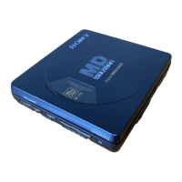
Electrical Parts List

Revision History

Related product manuals