1-4 (E)
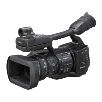
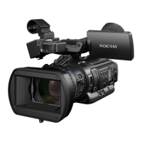
PMW-EX1R
1-3. Circuit Description
1. CMOS Block System
BI-202/203/204 Board
The BI-202, BI-203 and BI-204 boards are the rigid fl exible boards connecting the CMOS image sensors (IC1) to the
DPR-311 board.
The CMOS image sensor receives the three primary colors of R, G and B that are separated from the incoming light by the
prism. The CMOS image sensor converts the incoming primary color to electric signal. The built-in 12-bit column A/D
converters then convert the R, G and B analog video signals to the digital video signals respectively.
The electronic shutter, analog gain amplifi er and black level clamp functions are also provided in the above boards.
The BI-202 board is for the R-channel signal, the BI-203 board is for the G-channel signal and the BI-204 board is for the
B-channel signal.
The CMOS image sensor receives the sync signal and the serial communication signal from the DPR-311 board. The 12-bit
digital video signals that are supplied from the CMOS image sensors pass through the EMI fi lters (FL1 to FL4) and are
input to the DPR-311 board.
Various decoupling capacitors and the damping resistors are also mounted in the above boards.
IC3 of the BI-203 board is a temperature sensor that sends the temperature data to the CAMERA MICON (camera
μ-processor: IC500) on the DPR-311 board via I
2
C bus.
2. Camera Block System
DPR-311 Board
The DPR-311 board consists of the Camera Signal Processor IC (IC200) and the CAMERA MICON (camera μ-processor:
IC500) whereas the Camera Signal Processor IC (IC200) performs various processing on the digital video signal supplied
from the CMOS image sensor, and the CAMERA MICON (IC500) performs control of IC200 and other various controls
such as control of the CMOS image sensor and of lens. And the output digital video (Y/C) signal is sent to the next circuit
the video (baseband video) signal processing circuit.
The 12-bit digital video (RGB) signals supplied from the CMOS block (BI-202, BI-203 and BI-204 boards) fi rst enter the
camera signal processor IC (IC200). In the camera signal processor IC (IC200), average value, peak value of the RGB
digital video signals that are required for the following AUTO operations of the camera are detected.
The detected signals are sent to the CAMERA MICON (camera μ-processor: IC500).
. Auto white balance
. Auto black balance
. Auto focus
. Auto iris
. Auto knee
The digital video signal from the CMOS image sensor enters fi rst the selector circuit selecting either the digital video signal
from the CMOS image sensor or the internal TEST signal. The output video signal from the selector enters the compensa-
tion circuits consisting of the CMOS imager-related compensation circuit and the lens-related compensation circuit. The
video signal then receives the white balance processing, and the matrix signal and the detail signal are added to the video
signal. The video signal then receives the pedestal control, knee compensation, gamma correction and white/black clip
processing. The video signal fi nally enters the baseband processing IC (IC600).
The pixel number conversion processing from 1920/1080 to 1440/1080 or 1280/720 is also performed inside IC200.
 Loading...