2 (E)
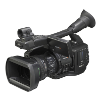
PMW-EX1R
4. Alignment
4-1. Servicing software “ServiceNavi-EX” ......................4-1 (E)
4-2. Preparation ................................................................4-1 (E)
4-2-1. Service Tools and Equipment ..........................4-1 (E)
4-2-2. Connection .......................................................4-1 (E)
4-3. MAINTENANCE Menu ........................................... 4-1 (E)
4-3-1. Test Saw Setting ...............................................4-1 (E)
4-3-2. Executing Auto Black Balance ........................4-2 (E)
4-3-3. Black Shading Adjustment...............................4-2 (E)
4-3-4. White Shading Adjustment ..............................4-3 (E)
4-3-5. Flare Adjustment .............................................. 4-5 (E)
4-3-6. Executing Auto FB Adjust ...............................4-6 (E)
4-4. RPN CORRECT Menu .............................................4-8 (E)
4-4-1. Executing Auto Detection ................................4-8 (E)
4-4-2. Correction Mode Settings ................................4-8 (E)
4-4-3. Channel Setting ................................................ 4-8 (E)
4-4-4. Cursor Setting ..................................................4-8 (E)
4-4-5. Cursor H Position Setting ................................4-9 (E)
4-4-6. Cursor V Position Setting ................................ 4-9 (E)
4-4-7. Operating Cursor Next ..................................... 4-9 (E)
4-4-8. Operating Cursor Prev ..................................... 4-9 (E)
4-4-9. Compensation Level Display ........................... 4-9 (E)
4-4-10. Executing Record .............................................4-9 (E)
4-4-11. Executing Delete ............................................4-10 (E)
4-4-12. Readout Mode Setting ...................................4-10 (E)
4-4-13. Executing Reset .............................................4-10 (E)
5. Spare Parts
5-1. Notes on Repair Parts ...................................................... 5-1
5-2. Exploded Views ...............................................................5-2
5-3. Supplied Accessories ..................................................... 5-18
6. Block Diagrams
Overall ............................................................................. 6-2
AU-326 ............................................................................ 6-3
AXM-42 ...................................................................... 6-3, 8
DAP-41................................................................6-3, 4, 6, 7
HN-356 ................................................................ 6-3, 4, 6, 7
HN-360 ............................................................................ 6-3
HN-361 ............................................................................ 6-3
KSW-55 ....................................................................... 6-3, 8
MA-183 ........................................................................... 6-3
SW-1478 ...................................................................... 6-3, 4
SWC-50 ........................................................................... 6-3
BI-202.............................................................................. 6-4
BI-203.............................................................................. 6-4
BI-204.............................................................................. 6-4
DPR-311 .............................................................. 6-4, 5, 6, 7
CN-3273 .................................................................... 6-5, 11
EC-68 .............................................................................. 6-5
DET-52 ............................................................................ 6-8
DR-644 ............................................................................ 6-8
HN-363 ............................................................................ 6-8
RM-224 ........................................................................... 6-8
CN-3258 .......................................................................... 6-9
DC-152 ............................................................................ 6-9
RE-272 ............................................................................ 6-9
CN-3259 ........................................................................ 6-10
RE-273 .......................................................................... 6-10
ASW-68 ......................................................................... 6-11
LED-491 ........................................................................ 6-11
LED-494 ........................................................................ 6-11
SW-1484 ........................................................................ 6-11
TX-131 .......................................................................... 6-12
VIF-46 ........................................................................... 6-12
7. Schematic Diagrams
Frame Wiring................................................................... 7-1

 Loading...