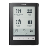
PRS-600
6
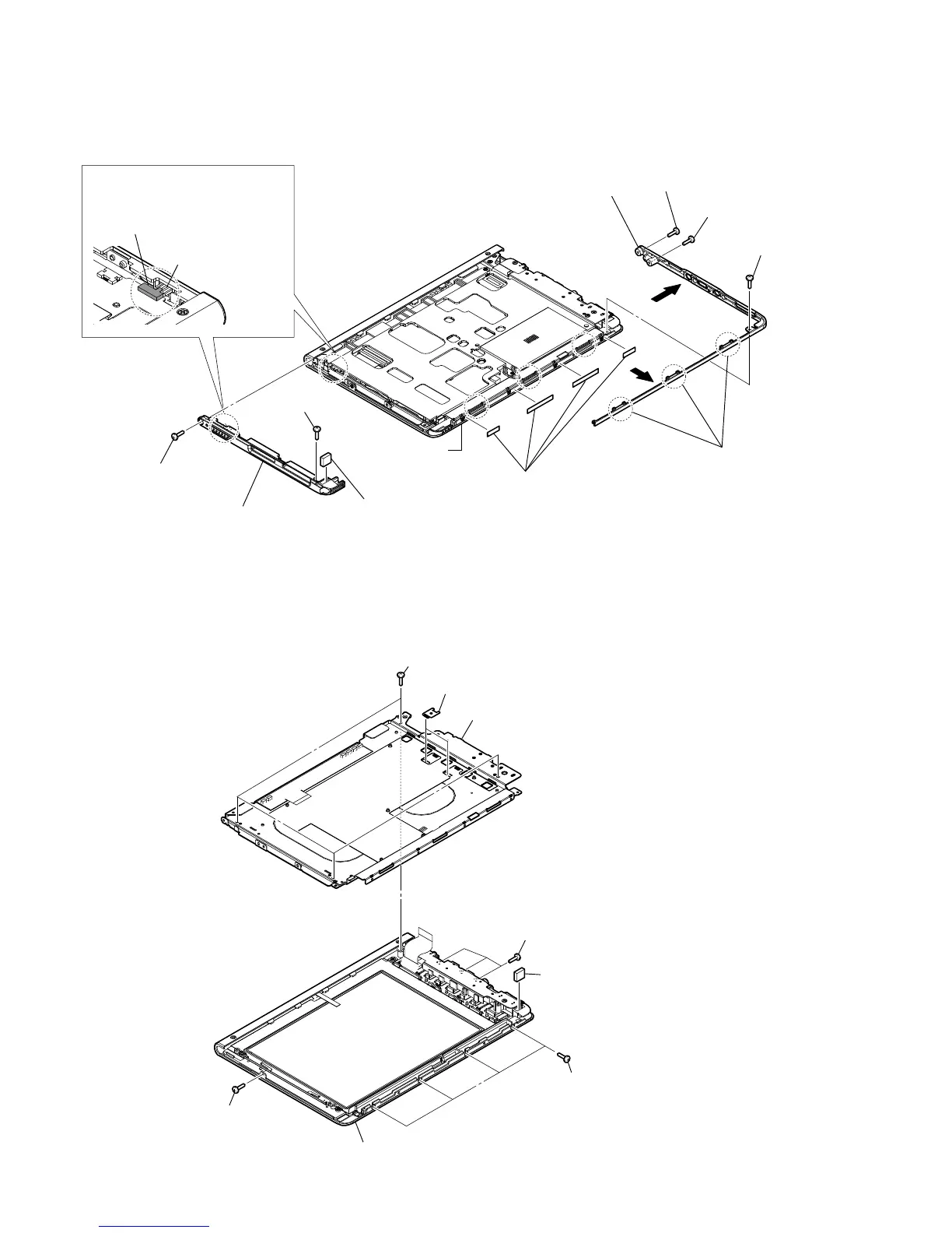
2-7. ORNAMENT_BOTTOM_ASSY, ORNAMENT_TOP_ASSY
Note 1: Ornament top assy can be disassembled only by working step 7 to 9.
2-8. CASE_UPPER_ASSY
2 screw (DIA. 1.4 u 1.8)
2 four screws
(DIA. 1.4 u 1.8)
3 four screws
4 chassis_assy block
2 three screws
(DIA. 1.4 u 1.8)
5 magnet block
Note: Pasted with adhesive tape.
6 case_upper_assy
(including touch screen)
1 two clips
1
screw (M1.4)
1
screw (M1.4)
3
three claws
4
4
6
ornament_bottom_assy
9
ornament_top_assy
7
screw (M1.4)
7
screw (M1.4)
8
magnet block
Note 3: Pasted with adhesive tape.
2 screw (P1.7 u 3)
power switch (S101)
knob_power
Note 2: Install the power switch (S101)
to fit to the knob_power.
touch screen side
5
adhesive (ORN_bottom)
(This is one part from 4 sections)