Do you have a question about the Sony PRS-T2 and is the answer not in the manual?
Lists supported book and picture file formats for the reader software and device.
Details operating systems and computing environment necessary for the Reader software.
States that mounted parts on boards cannot be exchanged individually; entire boards must be replaced.
Outlines steps for replacing the main board or chassis assembly, including LUT, SP1, and VCOM rewriting.
Advises confirming battery operation after soldering the battery to the main board.
Provides instructions for manually setting up a Wi-Fi connection after antenna replacement.
Illustrates the step-by-step order for disassembling the unit.
Details the procedure for removing the rear case block using a jig.
Explains how to remove the main board, including screw locations and component connections.
Explains the process of removing the case front assembly, including screws and claws.
Instructions for removing the battery assembly, including desoldering wires.
Details the removal of the light guide assembly using shafts.
Guides the removal of the jack board and chassis assembly, including FPC disconnection.
Lists prerequisites for entering the test mode, including PC and USB cable.
Step-by-step guide to initiating and entering the device's test mode.
Instructions for exiting the test mode and returning to normal operation.
Checks the device's display panel.
Tests the battery life of the device.
Checks the current status of the battery.
Resets the unit to its factory default settings.
Rewrites the LUT for screen parameters, especially after component replacement.
Rewrites the SP1 parameter file, specific to the FPL lot number.
Releases the device lock if it is effective.
Rewrites the VCOM voltage, which varies per device.
Exploded view of the rear case and its components.
Exploded view of the case front, battery, and chassis components.
Exploded view of the chassis assembly and its related parts.
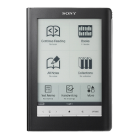
| Color | No |
|---|---|
| Technology | E Ink Pearl |
| Display diagonal | 6 \ |
| Grayscale levels | 16 |
| Display resolution | 600 x 800 pixels |
| Image formats supported | BMP, GIF, JPG, PNG |
| Video formats supported | - |
| Document formats supported | ePub, PDF, TXT |
| Compatible memory cards | MicroSD (TransFlash) |
| Maximum memory card size | 32 GB |
| Internal storage capacity | 1.3 GB |
| Battery voltage | 3.7 V |
| Battery life (max) | 1460 h |
| Battery recharge time | 2 h |
| Product color | Black |
| Minimum RAM | 512 MB |
| Minimum processor | 1GHz |
| Minimum storage drive space | 250 MB |
| Operating temperature (T-T) | 5 - 35 °C |
| Cables included | USB |
| Compatible operating systems | Windows 7 (32/64 bit), Windows 7 Starter, Windows 7 Home Basic, Windows 7 Home Premium, Windows 7 Professional, Windows 7 Ultimate, Windows Vista (32/64 bit), Windows XP 32 bit Mac OS X 10.7 (64 bit) + |
| Depth | 9.1 mm |
|---|---|
| Width | 110 mm |
| Height | 173 mm |
| Weight | 164 g |




 Loading...