PRS-T2
14
12. Reset Device Lock
When the Device Lock is effective, it can be released.
Note: When this mode is performed, it is necessary to reboot this unit and
to validate the settings. Touch the “Reboot (Normal)” in the test
mode menu.
Procedure:
1. Touch the “Reset Device Lock” in the test mode menu.
2. When the Device Lock is effective, the following screen is dis-
played.
Touch the “Yes”, the Device Lock becomes invalid.
It returns to the test mode menu when “No” is touched.
Test Mod
r
n:
.
.
Ta r
et stora
e: Internal
T
t P
n
l
pdate Waveform IR-LED L
v
l
Drawin
wit
nt
pdate SP
r
m
t
r
heck
Modul
TP
oordinat
heck
ser
stor
Test All Ke
witch ADB
Test Batter
Lif
Fake MoAke
V
r
i
on
irmatio
eboot
Normal
heck Batter
eboot
Recover
et
leep Timeou
a
o
o
ca
et
traces.txt
Factor
Initializ
e-fetch
I
ntifi
r
Lo
Extact
Flush
t D
vi
L
Power
f
Lo
Extact
hec
emperatur
Write V
M
WWAN
WWAN
FF
Reset Device Lock
Status: Locked.
Would you like to unlock?
Yes
No
(Screen display)
When the Device Lock is not effective, the following screen is
displayed. Touch the “OK”, return to the test mode menu.
Test Mod
V
r
i
n: X.X.
Ta r
et stora
e: Internal
T
t P
n
l
pdate Wave
orm IR-LED L
v
l
Drawin
wit
P
int
pdate SP
P
r
m
t
r
heck
Modul
TP
oordinat
heck
ser
istor
est
e
witch ADB
Test Batter
Lif
Fake MoAke
V
r
i
onfirmatio
eboot
Normal
heck Batter
eboot
Recover
et Sleep Timeou
adio Lo
ca
et “traces.txt
Factor
Initializ
e-
etch
I
nti
i
r
Lo
Extact
Flush
t D
vi
L
Power
Lo
Extact
hec
Temperatur
Write V
M
WWAN
WWAN
F
Reset Device Lock
Status: Unlocked.
OK
(Screen display)
13. Power Off
This mode is not used in servicing.
14. Log Extract 1
This mode is not used in servicing.
15. Check Temperature
This mode is not used in servicing.
16. Write VCOM
In this mode, the VCOM voltage can be rewritten.
The VCOM voltage for ELEMENT INK INDICATOR 6inch is
individually different.
Therefor, when replacing the complete MAIN board or CHASSIS
ASSY (including ELEMENT INK INDICATOR 6inch) you need
to rewrite the VCOM voltage.
Confi rmation:
The VCOM voltage confi rm method is different according to re-
placed parts.
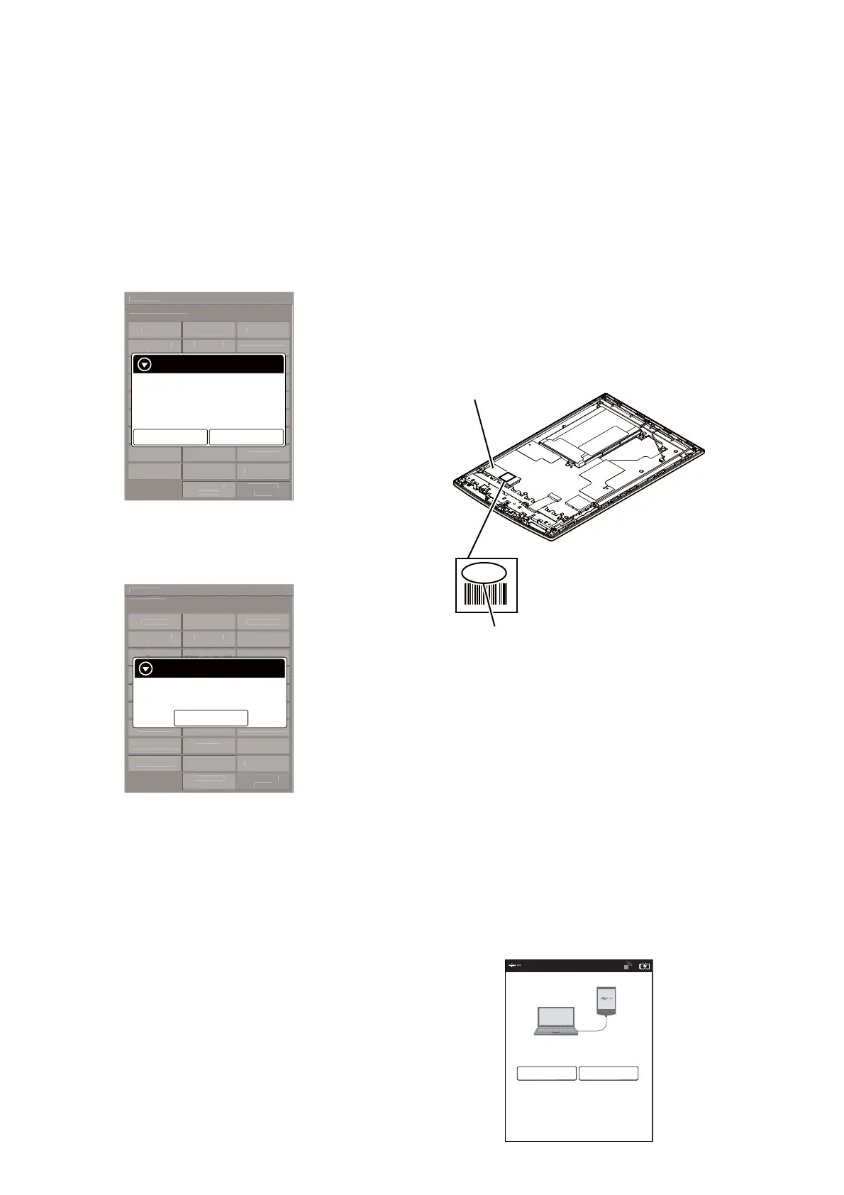
When the complete MAIN board is replaced:
Disassemble this unit until the VCOM voltage is seen (Refer to “2.
DISASSEMBLY” (pages 4 to 9)), and confi rm the VCOM volt-
age referring to the fi gure below. Record the confi rmed the VCOM
voltage by taking the memo etc..
-2.03
Flexible board of ELEMENT
INK INDICATOR 6inch
VCOM voltage
When the CHASSIS ASSY (including ELEMENT INK IN-
DICATOR 6inch) is replaced:
Confi rm the VCOM voltage described on the label of new CHAS-
SIS ASSY (including ELEMENT INK INDICATOR 6inch). Re-
cord the confi rmed the VCOM voltage by taking the memo etc..
Procedure:
1. Replace complete MAIN board or CHASSIS ASSY (including
ELEMENT INK INDICATOR 6inch) for new parts, and as-
semble this unit.
2. Make the text fi le on PC, and write the VCOM voltage re-
corded on memo etc..
Note 1: The VCOM voltage is described by the unit of mV that omits
minus.
(Example: Write “2030” when it is printed on the label as “–2.03 V”)
3. Press the [1] key to turn the power on.
4. Confi rm the HOME menu was completely displayed, and con-
nect this unit to PC by the USB cable (MICRO B).
5. Confi rm the USB connection screen displayed, and touch the
“Yes”.
Do you want the computer to recognize
this device?
Tap [Yes] to install Reader
TM
for PC or Reader
TM
for MacR
application, or transfer content.
Tap[No] to use Reader while charging.
Note: This screen will show whenever connecting with the
USB cable.
OFF
Yes No