PRS-T2
13
11. Update SP1 Parameters
In this mode, the SP1 parameter fi le can be rewritten.
The SP1 parameter fi le is individually different by the FPL lot
number of ELEMENT INK INDICATOR 6inch.
Therefor, when replacing the complete MAIN board or CHASSIS
ASSY (including ELEMENT INK INDICATOR 6inch) you need
to rewrite the SP1 parameter fi le.
Confi rmation:
The FPL lot number confi rm method is different according to re-
placed parts.
When the complete MAIN board is replaced:
Disassemble this unit until the FPL lot number is seen (Refer to “2.
DISASSEMBLY” (pages 4 to 9)), and confi rm the FPL lot number
referring to the fi gure below. Record the confi rmed the FPL lot
number by taking the memo etc..
E4KR28C01L5V00111AT
ED060SCE(LF)C1 FME60B5060(E120)
FPL lot number
Flexible board of ELEMENT
INK INDICATOR 6inch
When the CHASSIS ASSY (including ELEMENT INK IN-
DICATOR 6inch) is replaced:
Confi rm the FPL lot number described on the label of new CHAS-
SIS ASSY (including ELEMENT INK INDICATOR 6inch). Re-
cord the confi rmed the FPL lot number by taking the memo etc..
Procedure:
1. Replace complete MAIN board or CHASSIS ASSY (including
ELEMENT INK INDICATOR 6inch) for new parts, and as-
semble this unit.
2. Confi rm the following data to the service headquarters.
• SP1 parameter fi le corresponding to the recorded FPL lot
number
3. Rename the fi le obtained in step 2 to “sp1.bin”.
4. Press the [1] key to turn the power on.
5. Confi rm the HOME menu was completely displayed, and con-
nect this unit to PC by the USB cable (MICRO B).
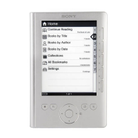
6. Confi rm the USB connection screen displayed, and touch the
“Yes”.
Do you want the computer to recognize
this device?
Tap [Yes] to install Reader
TM
for PC or Reader
TM
for MacR
application, or transfer content.
Tap[No] to use Reader while charging.
Note: This screen will show whenever connecting with the
USB cable.
OFF
Yes No
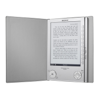
7. The following screen is displayed in this unit, and confi rm the
“READER” drive of this unit is recognized on PC.
This device is correctly recognized by the
computer.
Check completion of the transfer by computer before
detaching USB cable.
8. Make the following folder under the “READER” drive of this
unit.
/testmode/data/
9. Copy the “sp1.bin” to the “data” folder made in step 8.
10. Remove this unit and USB cable (MICRO B) from PC.
11. Enter the test mode (Refer to “HOW TO ENTER THE TEST
MODE” (page 10)).
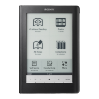
12. Touch the “Update SP1 Parameters” in the test mode menu.
Test Mod
r
i
n: X.X.
Ta r
et stora
e: Internal
t
n
pdate Wave
orm
-
v
Drawin
wit
P
int
pdate
P
P
r
m
t
r
heck
Modul
TP
oordinat
heck
ser
istor
Test All Ke
witch ADB
Test Batter
Li
ake MoAke
r
i
on
irmatio
eboot
Normal
heck Batter
eboot
Recover
et Sleep Timeou
adio Lo
ca
et “traces.txt
actor
n
t
a
z
e-
etch
I
nti
i
r
Lo
Extact
Flush
t D
vi
L
Power
Lo
Extact
hec
Temperatur
Write V
M
WWAN
WWAN
FF
Update SP1 Parameters
Would you like to update?
Yes
No
(Screen display)
13. Touch the “Yes”, it starts rewriting the SP1 parameter.
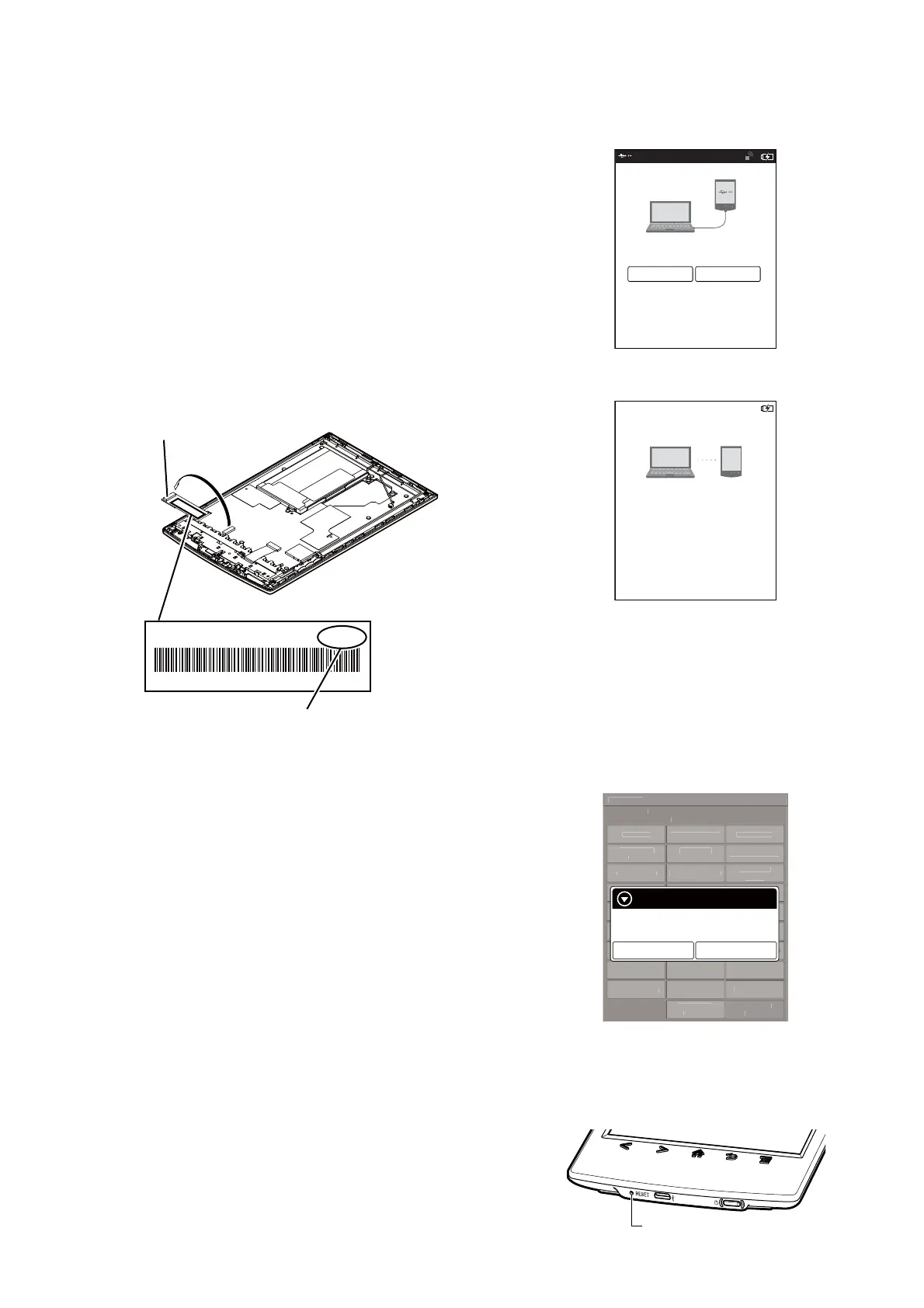
14. When SP1 parameter is updated, “success” is displayed.
15. Press [RESET] button and reboot this unit.
[RESET] button
16. The SP1 parameter fi le rewriting is completed.