7-1
SECTION 7
ADJUSTMENT
RDR-HX510
7-1. Video System Adjustment
Preparing for Adjustment
1. Equipments
• Oscilloscope
• Reference Disk
HLX-507 (PAL single layer disk) J-6090-077-A
HLX-506 (PAL dual layer disk) J-6090-078-A
1. Video Levl Adjustment (RD-053 Board)
<Purpose>
This adjustment is made to satisfy the PAL standard, If it is adjusted
incorrectly, brightness will be too bright or too dark.
Mode Video level adjustment in test mode
Signal Color bars
Test point LINE OUT (VIDEO) connector
(terminated in 75 Ω)
Instrument Oscilloscope
Adjusting element RV801
Specification 1.0 Vp-p
Adjusting method:
1) Insert the reference disk and play back the 100% color bars.
2) Adjust RV801 for 1.0 Vp-p.
Fig. 7-1.
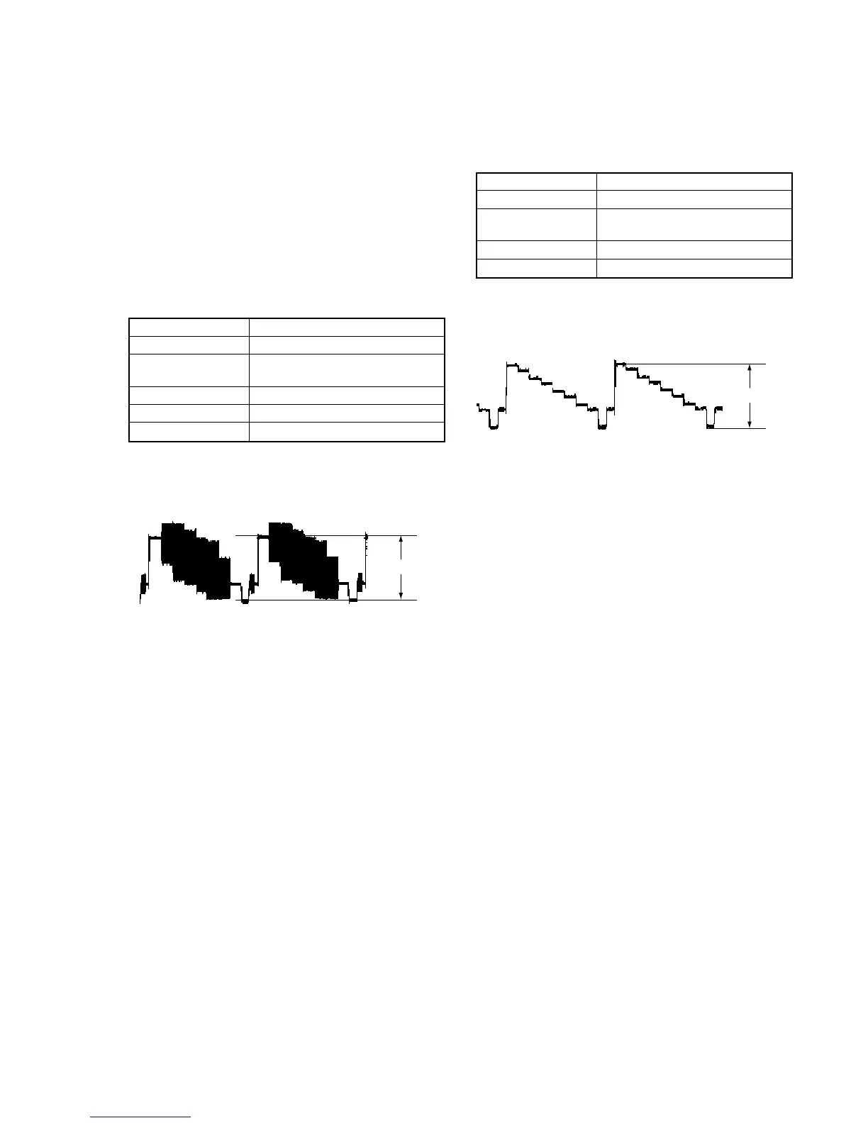
7-2. S-Video Output S-Y Check
<Purpose>
This check confirms that the S-video output. If it adjusted incorrectly,
color will be to dark or too thin.
Mode Video level adjustment in test mode
Signal Color bars
Test point S VIDEO OUT (S-Y) connector
(terminated in 75 Ω)
Instrument Oscilloscope
Specification 1.0 ± 0.06Vp-p
Adjusting method:
1) Insert the reference disk and play back the 100% color bars.
2) Confirm that the S-Y level is 1.0 ± 0.06 Vp-p.
1.0 Vp-p
+ 0.04
– 0.02
Fig. 7-2.
1.0
±
0.06Vp-p
 Loading...