SERVICE MANUAL
Sony Corporation
Published by Sony EMCS (Malaysia) PG Tec
HT-CT290/CT291
SA-CT290/CT291
SPECIFICATIONS
HT-CT290/CT291
SOUND BAR
SA-CT290/CT291
ACTIVE SPEAKER SYSTEM
9-890-685-01
2017B80-1
©
2017.02
US Model
Canadian Model
E Model
Australian Model
HT-CT290/SA-CT290
AEP Model
UK Model
HT-CT290/CT291/SA-CT290/CT291
Ver. 1.0 2017.02
• All the units included in the HT-
CT290/CT291 (SA-CT290/CT291,
SA-WCT290/WCT291, remote
control) are required to confi rm the
operation of SA-CT290/CT291.
Check in advance that you have
all the units.
COMPONENT MODEL NAME
HT-CT290 HT-CT291
Bar Speaker (Active Speaker System) SA-CT290 SA-CT291
Subwoofer (Active Subwoofer) SA-WCT290 SA-WCT291
• The service manual for SA-WCT290/WCT291 has been issued separately.
Please refer to the service manual for information.
Note:
Be sure to keep your PC used for service and
checking of this unit always updated with the
latest version of your anti-virus software.
In case a virus affected unit was found during
service, contact your Service Headquarters.
Bar Speaker (SA-CT290/
SA-CT291)
Amplifi er section
US models:
POWER OUTPUT AND TOTAL HARMONIC
DISTORTION:
(FTC)
Front L + Front R:
With 4 ohms loads, both channels
driven, from 200 Hz – 20,000 Hz;
rated 15 watts per channel minimum
RMS power, with no more than
1% total harmonic distortion from
250 milliwatts to rated output.
POWER OUTPUT (reference)
Front L/Front R: 100 W (per channel at
4 ohms, 1 kHz)
Other models:
POWER OUTPUT (rated)
Front L + Front R:
30 W + 30 W (at 4 ohms, 1 kHz, 1% THD)
POWER OUTPUT (reference)
Front L/Front R: 100 W (per channel at
4 ohms, 1 kHz)
Inputs
USB
TV IN OPTICAL
Output
HDMI OUT TV (ARC)
HDMI section
Connector
Type A (19pin)
USB section
(USB) port
Type A
BLUETOOTH section
Communication system
BLUETOOTH Specification version
4.2
Output
BLUETOOTH Specifi cation Power
Class 1
Maximum communication range
Line of sight approx. 25 m (82 ft)
1)
Frequency band
2.4 GHz band (2.4000 GHz –
2.4835 GHz)
Modulation method
FHSS (Freq Hopping Spread
Spectrum)
Compatible BLUETOOTH profiles
2)
A2DP 1.2 (Advanced Audio
Distribution Profile)
AVRCP 1.6 (Audio Video Remote
Control Profile)
Supported Codecs
3)
SBC
4)
Transmission range (A2DP)
20 Hz – 20,000 Hz (Sampling
frequency 32 kHz, 44.1 kHz, 48 kHz)
1)
The actual range will vary depending on
factors such as obstacles between devices,
magnetic fields around a microwave
oven, static electricity, cordless
phone, reception sensitivity, antenna’s
performance, operating system, software
application, etc.
2)
BLUETOOTH standard profiles
indicate the purpose of BLUETOOTH
communication between devices.
3)
Codec: Audio signal compression and
conversion format
4)
Subband Codec
Front L/Front R speaker section
Speaker system
Full range speaker system, Acoustic
suspension
Speaker
40 mm (1
5
/
8
in) × 100 mm (4 in) cone
type × 2
General
Power requirements
US, CND models:
120 V AC, 60 Hz
LA9 models:
110 V – 240 V AC, 50/60 Hz
EA models:
127 V – 240 V AC, 50/60 Hz
Other models:
220 V – 240 V AC, 50/60 Hz
Power consumption
On: 40 W
Standby: 0.5 W or less (Power saving
mode)
(When Control for HDMI function and
BLUETOOTH Standby mode are
set to off)
Standby: 2.8 W or less
5)
(When Control for HDMI function and
BLUETOOTH standby mode are set to
on)
Dimensions (w/h/d) (approx.)
900 mm × 52 mm × 86 mm
(35
1
/
2
in × 2
1
/
8
in × 3
1
/
2
in)
Mass (approx.)
2.3 kg (5 lb 2 oz)
5)
The system will automatically enter
Power saving mode when there is no
HDMI connection and no BLUETOOTH
pairing history.
Wireless transmitter/
receiver section
Frequency band
2.4 GHz (2.4000 GHz – 2.4835 GHz)
Modulation method
FHSS (Freq Hopping Spread
Spectrum)
Supplied accessories
Remote control (1)
R03 (size AAA) batteries (2)
Optical digital cable (1)
WALL MOUNT TEMPLATE (1)
Speaker pads for the subwoofer (4)
Refer to the supplied Operating Instructions on
installing the subwoofer horizontally.
Conversion Adaptor (2)
The adaptor is not use in Chile, Uruguay and
Paraguay. Use the adaptor in the countries
where it is neccessary.
Design and specifications are subject to
change without notice.
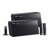
Photo: SA-CT290 (Black)
Photo: SA-CT290 (White) / SA-CT291