SLT-A65/A65K/A65L/A65M/A65V/A65VK/A65VL/A65VM/A65VX/A65VY/A65X/A65Y_L2
2-1
2. REPAIR PARTS LIST
Follow the disassembly in the numerical order given.
IDENTIFYING PARTS
Link
• Abbreviation
AUS : Australian model
CH : Chinese model
CND : Canadian model
J : Japanese model
JE : Tourist model
KR : Korea model
(ENGLISH)
NOTE:
• -XX, -X mean standardized parts, so they may have some differences from the original one.
• Items marked “∗” are not stocked since they are seldom required for routine service. Some delay
should be anticipated when ordering these items.
• The mechanical parts with no reference number in the exploded views are not supplied.
• Due to standardization, replacements in the parts list may be different from the parts specified
in the diagrams or the components used on the set.
(JAPANESE)
【使用上の注意】
• -XX,-Xは標準化部品のため,セットに付いている部品と異なる場合があります。
• ∗印の部品は常備在庫しておりません。
• ここに記載されている部品は, 補修用部品であるため,回路図及びセットに付いている部品と
異なる場合があります。
図面番号で部品を指定するときは基板名
又はブロックを併せて指定してください。
お願い
• Color Indication of Appearance Parts
Example:
(SILVER) : Cabinet’s Color
(Silver) : Parts Color
• 外装部品色表示
例:
(SILVER):セットの色を表す。
(Silver) :部品の色を表す。
The components identified by mark 0 or
dotted line with mark 0 are critical for safety.
Replace only with part number specified.
Les composants identifiés par une marque
0 sont critiques pour la sécurité.
Ne les remplacer que par une pièce portant
le numéro spécifié.
0
印の部品,または
0
印付の点線で囲ま
れた部品は,安全性を維持するために,
重要な部品です。
従って交換時は,必ず指定の部品を使用
してください。
When indicating parts by reference number,
please include the board name.
View Position
Right View
Left View
Front View
Bottom View
Top View
Back View
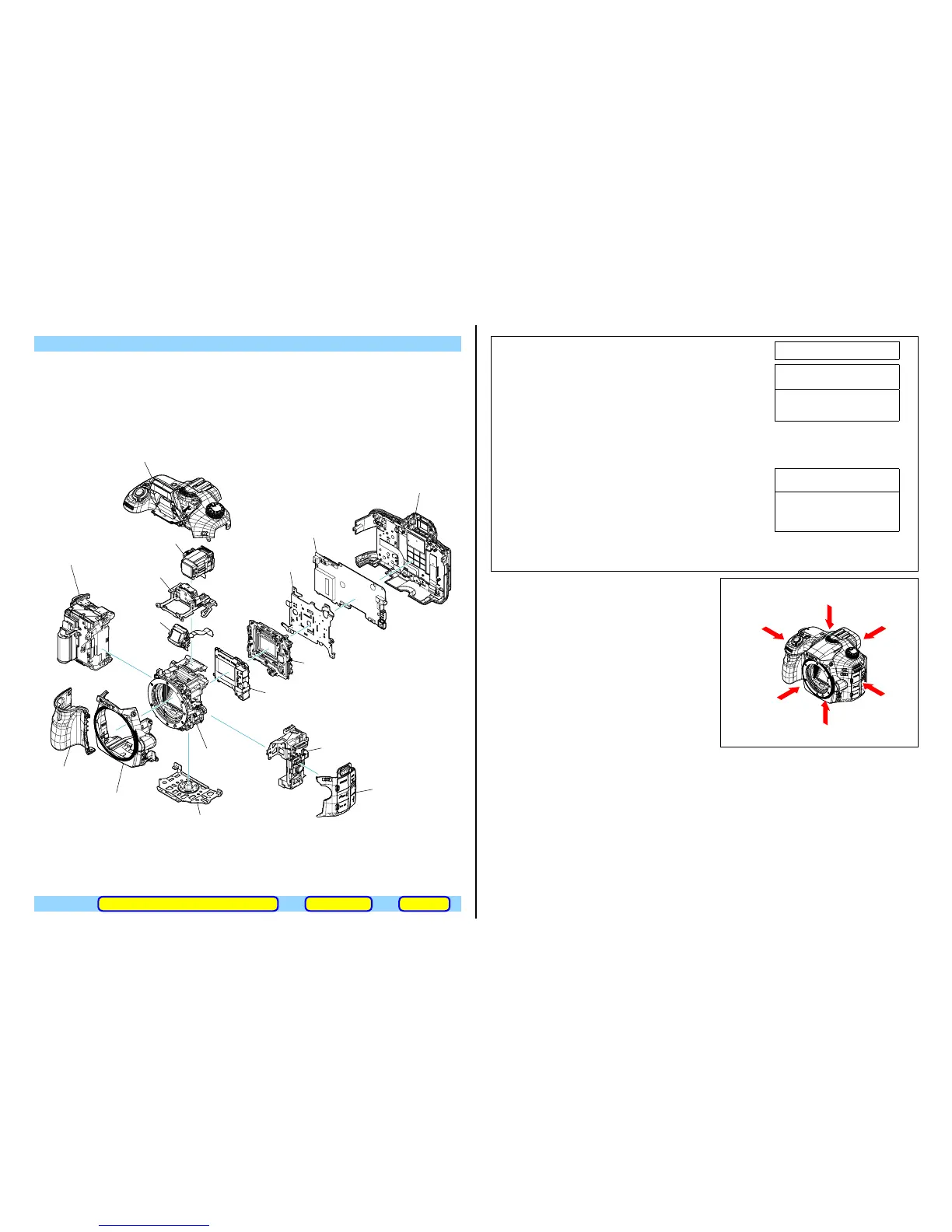
AM-026
1 Rear Cover Section
• PD-444 Board
• SHD-003 (868) Flexible Board
• LCD-022 Flexible Board
4 Top Cover Section
• GP868 Assy (A65V/A65VK/A65VL/A65VM/A65VX/A65VY)
• SHM-002 Flexible Board
5 EVF Block
• EYE-012 Flexible Board
2 CV Side Cover (L) Assy
qd Shutter Unit
(AFE-3032)
qg ALX-8630
(AF Module)
6 AM-026 Board
3 CV Grip Cover Assy
8 CV Front Cover Assy
9 BD Top Frame Assy
q; BD Bottom Frame Assy
7 BD AM Heatsink Plate
qa Jack Holder Block
• RM-100 Flexible Board
qs Jack Holder Block
• IM Imager Unit
• ISP-004 Flexible Board
• ISL-005 Flexible Board
qf Battery Holder Section
• GO-001 Board
• MCR-001 Flexible Board
qh Mirror Box Section
ACCESSORIESDISCHARGING OF THE CHARGING CAPACITOR ASSEMBLY
The changed portions from
Ver. 1.5 are shown in blue.
Ver. 1.6 2013.07