SLT-A65/A65K/A65L/A65M/A65V/A65VK/A65VL/A65VM/A65VX/A65VY/A65X/A65Y_L2
2-4
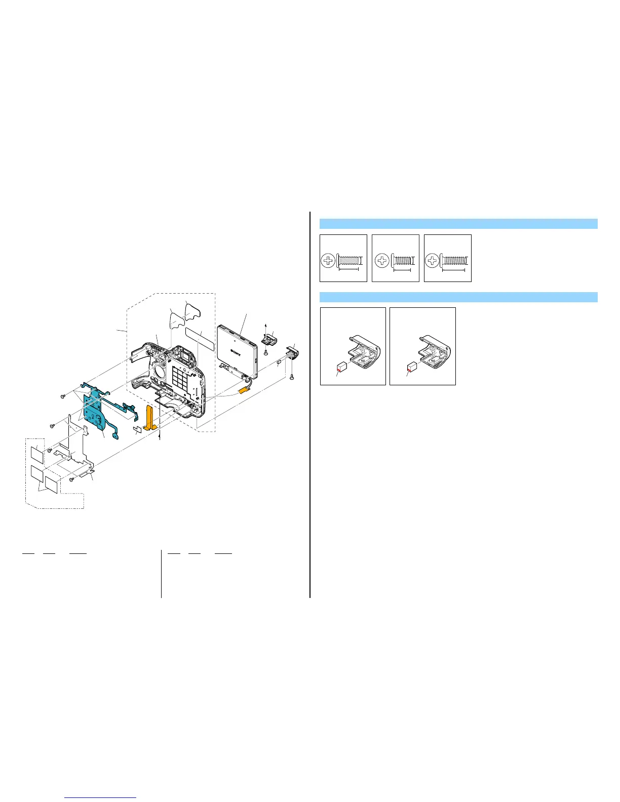
2-1-2. REAR COVER SECTION
ns: not supplied
Ref. No. Part No. Description
Ref. No. Part No. Description
A
A
LCD Section
(See page 2-5)
#2
#12
#12
#5
#5
ns
ns
#2
ns
51
52
53
55
57
54
56
60
59
58
(Note)
A65V/A65VK/A65VL/
A65VM/A65VX/A65VY
Screw
#2: M1.7 X 4.0
(Black)
2-635-562-31
4.0
1.7
#5: M1.7 X 3.5 (Tapping)
(Black)
3-080-204-01
3.5
1.7
#12: M1.7 X 5.0 (Tapping)
(Black)
3-080-204-21
1.7
5.0
51 4-293-742-01 EM REAR GROUND PLATE L
52 1-884-618-11 SWITCH BLOCK, CONTROL (RS86800)
53 4-293-743-01 SHEET, CV FPC COVER
54 X-2582-405-1 CV REAR COVER ASSY
∗ 55 4-293-750-01 CV REAR RUBBER TAPE
∗ 56 4-293-749-01 CV REAR RUBBER
∗ 57 4-257-255-01 CV REAR CAUTION LABEL
58 1-471-504-11 MAGNET (ND5X3.5X2.4-B) (Note)
59 4-293-744-01 CV O HINGE COVER L
60 4-293-745-01 CV O HINGE COVER G
#2 2-635-562-31 SCREW (M1.7)
#5 3-080-204-01 SCREW, TAPPING, P2
#12 3-080-204-21 SCREW, TAPPING, P2
Note
Note :
Install the magnet with
the marking oriented
as shown below.
Marking
Note :
マグネットを取付ける
際は,マ−キング面を
図の位置にあわせて
ください。
マーキング
The changed portions from
Ver. 1.5 are shown in blue.
Ver. 1.6 2013.07