SLT-A65/A65K/A65L/A65M/A65V/A65VK/A65VL/A65VM/A65VX/A65VY/A65X/A65Y_L2
2-10
1
IM SHEET GRAPHITE
→
#12 X 4
Back View
#12
#12
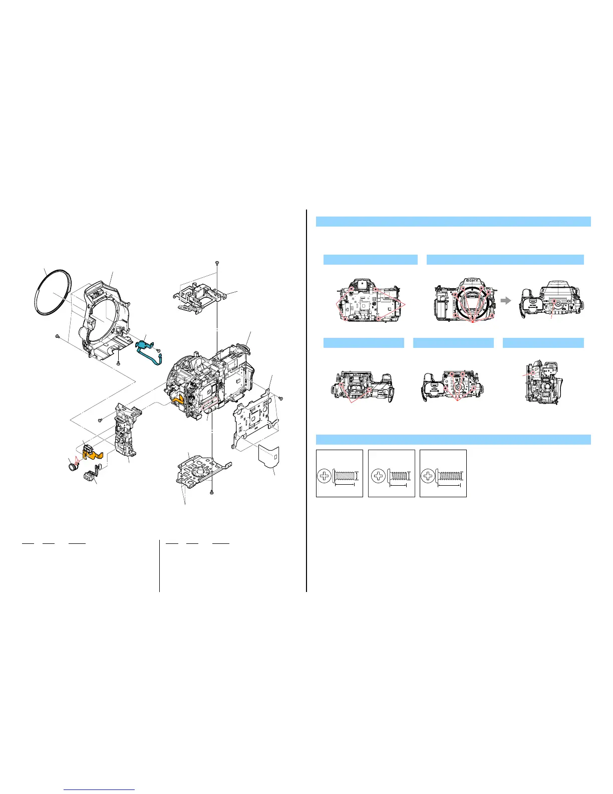
2-1-8. FRONT COVER SECTION
Screw
#2: M1.7 X 4.0
(Black)
2-635-562-31
4.0
1.7
#5: M1.7 X 3.5 (Tapping)
(Black)
3-080-204-01
3.5
1.7
Ref. No. Part No. Description
Ref. No. Part No. Description
#12
#1
#12
#12
#2
#5
SP901
J901
#12
1 359
360
351
353
355
2 352
3 354
4 358
5 357
Shutter Unit Section
(See page 2-11)
1
#12: M1.7 X 5.0 (Tapping)
(Black)
3-080-204-21
1.7
5.0
351 4-293-695-01 CV DECO RING
352 X-2582-401-1 CV FRONT COVER ASSY
353 1-884-054-11 SWITCH BLOCK, CONTROL (FS86800)
354 X-2582-399-1 BD TOP FRAME ASSY (868)
355 A-1837-195-A RM-100 FLEXIBLE BOARD, COMPLETE
357 X-2582-393-1 BD JACK HOLDER ASSY (868)
358 X-2582-398-1 BD BOTTOM FRAME ASSY
359 4-293-608-01 BD AM HEATSINK PLATE
360 4-296-655-01 BD LIGHT GUARD SHEET
J901 1-821-194-51 JACK, DC
SP901 1-826-403-61 LOUDSPEAKER (1.0CM)
#2 2-635-562-31 SCREW (M1.7)
#5 3-080-204-01 SCREW, TAPPING, P2
#12 3-080-204-21 SCREW, TAPPING, P2
DISASSEMBLY
1. Remove in numerical order (1 to 5) in the left figure.
2. The meaning of the symbol in left figure is as follows. Be careful when you remove it.
◇: Solder
5 #12 X 1
Left View
#12
4 #12 X 43 #12 X 2
Top View
#12
Bottom View
#12
2 #12 X 6 → #2 X 1
Front View Bottom View
#12
#2