SLT-A65/A65K/A65L/A65M/A65V/A65VK/A65VL/A65VM/A65VX/A65VY/A65X/A65Y_L2
3-1
3. ASSEMBLY
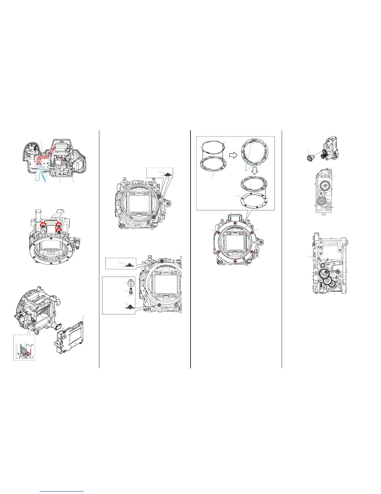
Assembly-1: Routing of the Flash Harness.
Ta pe
Flash Harnesses
Connector
Ribs
Assembly-2: Assemble ALX-8630 (AF Module)
A Tighten the S Adjustment Screws completely.
B Loosen the S Adjustment Screws evenly by 1.5 turns.
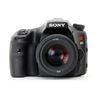
Assembly-3: Assemble Shutter Unit (AFE-3032)
When install Shutter Unit (AFE-3032), check MB Shutter Charge
Lever is downward.
Shutter Unit
(AFE-3032)
MB Shutter
Charge Lever
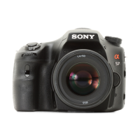
4-3. MB Ring SP COM, MB Mount Spacer, H Mount
3
6
1
4
2
5
MB Ring SP COM
MB H Mount
MB Mount Spacer
GG-85
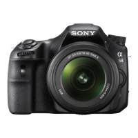
4-4. AP Sensor Gear Setting Position.
P Sensor Gear
AP Sensor Gea
Hole
4-5. Gears Setting Position.
MB Shutter
Charge SP
MB Shutter Charge
Camgear Assy
MB Shutter
Charge Leve
MB Lever
Cushion
MB Deceleration
Gear 1
MB Deceleration
Gear 2
Assembly-4: Mirror Box Sub Unit
4-1. Ring Roller (A) (SV), AP Iris Ring
A Attach the Ring Roller (A) (SV) to the MB Front Frame Assy.
When attaching the Ring Roller (A) (SV), be sure to
remove the AP Iris Ring beforehand.
B Attach the AP Iris Ring by aligning it with the stop position
(iris-in end) of drawing.
Stop Position (iris-in end)
Ring Roller (A) (SV)
Ring Roller (A) (SV)
AP Iris Ring
4-2. Ring Roller (B) (SV), AP Ring Roller C,
Ring Roller Shaft (C) (SV)
AP Iris Ring
Ring Roller (B) (SV)
Ring Roller (B) (SV)
GG-85
Ring Roller Shaft (C) (SV)
AP Ring Roller C
AP Iris Ring
Ring Roller Shaft (C) (SV)
AP Ring Roller C
P Ring Roller C
Ring Roller Shaft (C) (SV)
The changed portions from
Ver. 1.4 are shown in blue.
Ver. 1.5 2012.11