Do you have a question about the Sony SLV-E270CP and is the answer not in the manual?
Basic technical details of the VCR model.
List of items included with the VCR.
Critical warning for safety-related components.
Guide to configuring the remote control.
Instructions for connecting and tuning the VCR to a TV.
Instructions for operating the VCR with a tape.
Step-by-step guide to disassembling the VCR's main components.
Procedures for VCR mechanism maintenance and checks.
Detailed guide for adjusting the tape path.
Explanation of the VCR's self-diagnosis system.
Procedure for adjusting the VCR's servo circuit.
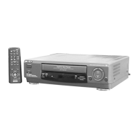
Visual breakdown of external VCR components.
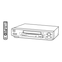
Visual breakdown of internal mechanism parts.
| Type | VCR |
|---|---|
| Recording Speed | SP, LP |
| Playback Speed | SP, LP |
| Tuner | Yes |
| Number of Heads | 4 |
| Remote Control | Yes |
| Smart Recording | Yes |
| Connections | RF |
| Inputs | RF |
| Outputs | RF |