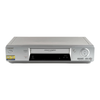
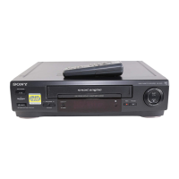
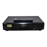
EasyManua.ls Logo

Sony SLV-SE630 User Manual

Sony SLV-SE630
70 pages
To Next Page IconTo Next Page
Page #1 background imageLoading...
Page #1 background image
Photo: SLV-SE830N
RMT-V407A
— Continued on next page —
AEP Model
SLV-SE230B/SE230D/SE430K/SE630B/SE630D/SE630E/SE630N/
SE730B/SE730D/SE730E/SE730N/SE737E/SE830B/SE830D/
SE830E/SE830N/SX730D/SX730E/SX730N/SX737D
UK Model
SLV-SE230G/SE230I/SE730G/SE730I/SE830G
SERVICE MANUAL
VIDEO CASSETTE RECORDER
TS-10 MECHANISM
Refer to the SERVICE MANUAL of VHS MECHANI-
CAL ADJUSTMENT MANUAL VII for MECHANICAL
ADJUSTMENTS. (9-921-790-11)
SPECIFICATIONS
SLV-SE230/SE430/SE630/SE730/SE737/
SE830/SX730/SX737
RMT-V405/V405A/V406/V406A/V406B/V407A/V407B/V407C
System
Colour system
SE230B/SE630B/SE730B/SE830B:
SECAM (L)
VHF F2 to F10
UHF F21 to F69
CATV B to Q
HYPER S21 to S41
PAL (B/G)
VHF E2 to E12
VHF italian channels A to H
UHF E21 to E69
CATV S01 to S05, S1 to S20
HYPER S21 to S41
SE230D/SE630D/SE630E/SE730D/SE730E/
SE737E/SE830D/SE830E/SX730D/SX730E/
SX737D:
PAL (B/G)
VHF E2 to E12
VHF italian channels A to H
UHF E21 to E69
CATV S01 to S05, S1 to S20
HYPER S21 to S41
SE230G/SE730G/SE830G:
PAL (I)
UHF B21 to B69
SE230I/SE730I:
PAL (I)
VHF IA to IJ, SA10 to SA13
UHF B21 to B69
CATV S01 to S05, S1 to S20
HYPER S21 to S41
SE430K/SE630N/SE730N/SE830N/SX730N:
PAL (B/G, D/K)
VHF E2 to E12, R1 to R12
UHF E21 to E69, R21 to R69
CATV S1 to S41, S01 to S05
RF output signal
SE230D/SE230G/SE230I/SE430K/SE630D/
SE630E/SE630N/SE730D/SE730E/SE730G/
SE730I/SE730N/SE737E/SE830D/SE830E/
SE830G/SE830N/SX730D/SX730E/SX730N/
SX737D:
UHF channels 21 to 69
Aerial out
75-ohm asymmetrical aerial socket
Tape speed
SE230B:
SP: PAL 23.39 mm/s (recording/playback)
NTSC 33.35 mm/s (playback only)
SECAM
23.39 mm/s (recording/playback)
MESECAM
23.39 mm/s (playback only)
LP: NTSC 16.67 mm/s (playback only)
SECAM
11.70 mm/s (recording/playback)
MESECAM
11.70 mm/s (playback only)
SE230D:
SP: PAL 23.39 mm/s (recording/playback)
NTSC 33.35 mm/s (playback only)
LP: NTSC 16.67 mm/s (playback only)
SE230G/SE230I/SE630D/SE630E/SE730D/
SE730E/SE730G/SE730I/SE737E/SE830D/
SE830E/SE830G/SX730D/SX730E/SX737D:
SP: PAL 23.39 mm/s (recording/playback)
NTSC 33.35 mm/s (playback only)
LP: PAL 11.70 mm/s (recording/playback)
NTSC 16.67 mm/s (playback only)
EP: NTSC 11.12 mm/s (playback only)

Table of Contents

Questions and Answers:

Sony SLV-SE630 Specifications

General IconGeneral
BrandSony
ModelSLV-SE630
CategoryVCR
LanguageEnglish

Summary

SERVICE MANUAL

SPECIFICATIONS

Details about colour systems, RF output, aerial out, and tape speed.

SAFETY CHECK-OUT

Steps to perform after service to ensure safe operation for the customer.

1. GENERAL

Getting Started

Introduction to the manual and initial setup procedures.

Index to parts and controls

References to pages detailing specific parts and controls.

2. Setting up the remote commander

Using the remote commander

How to use the remote commander for VCR and TV operations.

3. Connecting the VCR

Connecting to a VCR or stereo system

Instructions for connecting the VCR to other audio/video devices.

4. Setting up the VCR with the Auto Set Up function

5. Selecting the TV system

How to select the appropriate TV system for optimal performance.

Presetting channels

Changing/disabling programme positions

How to rearrange or disable preset channel positions.

Basic Operations

Playing a tape

How to insert and play a video tape.

Recording TV programmes

Instructions for recording TV programmes.

Additional Operations

Playing/searching at various speeds

How to play or search tapes at different speeds.

Adjusting the picture

Reducing the VCR's power consumption

Settings to reduce power usage when the VCR is in standby.

Editing

Basic editing

Steps for performing basic editing tasks like dubbing.

Troubleshooting

Power

Troubleshooting common power-related issues.

Clock

Troubleshooting problems related to the VCR's clock function.

Playback

Troubleshooting common playback problems.

Quick Start Guide

1 Connecting the VCR

Basic steps for connecting the VCR to a TV and power.

2 Using the Auto Set Up function

Initial automatic setup for channels and settings.

3 Setting the clock

Setting the correct time and date for timer functions.

2. DISASSEMBLY

2-1 MONO MODELS

Disassembly instructions for mono models.

2-2 Hi-Fi MODELS

2-2-1 Cabinet Top

Steps to remove the cabinet top for Hi-Fi models.

3. P.C.BOARDS

3-1 Main PCB (Main A model)

Location and details of the Main PCB for Main A models.

4. SCHEMATIC DIAGRAMS

Block Identification of Main PCB

Block diagram showing functional areas of the Main PCB.

4-1 S.M.P.S. (Main A model)

4-2 S.M.P.S. (Main B model)

Schematic diagram of the Switched-Mode Power Supply for Main B models.

4-3 POWER (Main A model)

4-4 POWER (Main B model)

Schematic diagram of the Power Drive Block for Main B models.

4-5 SYSTEM CONTROL/SERVO (Main A model)

4-6 SYSTEM CONTROL/SERVO (Main B model)

Schematic diagram of the System Control/Servo for Main B models.

4-7 AUDIO/VIDEO

4-8 Hi-Fi (Hi-Fi model)

Schematic diagram for the Hi-Fi audio section.

4-9 TM-BLOCK

4-10 OSD/VPS/PDC

Schematic diagram for On-Screen Display, VPS, and PDC functions.

4-11 SECAM (SE230B/SE630B/SE730B/SE830B)

4-12 A2/NICAM (Hi-Fi model)

Schematic diagram for the A2/NICAM audio system in Hi-Fi models.

4-13 INPUT-OUTPUT (2 SCART JACK) (Main A model)

4-14 INPUT-OUTPUT (2 SCART JACK) (Main B model)

Schematic diagram for input/output via SCART connectors for Main B models.

4-15 FUNCTION (SE630)

4-16 FUNCTION (Main B model)

Schematic diagram for the function block of Main B models.

5. ALIGNMENT AND ADJUSTMENT

5-1 REFERENCE

General reference for adjustment procedures and remote control buttons.

5-1-2 Test point location for adjustment mode setting (Mono model)

5-1-3 SW7T01 (TEST) location for adjustment mode setting (Hi-fi model)

Locates the TEST switch (SW7T01) on the Function PCB for adjustment mode.

5-2 MECHANICAL ADJUSTMENT

5-2-1 The number and position of test point

Identifies test points for mechanical adjustments.

5-2-2 ACE Head Position (X-Point) Adjustment

Procedure to adjust the ACE Head Position (X-Point).

5-3 HEAD SWITCHING POINT ADJUSTMENT

5-4 NVRAM OPTION SETTING

Steps to set NVRAM option numbers for model compatibility.

6. REPAIR PARTS LIST

6-1 Exploded Views

Visual breakdown of parts for disassembly and replacement.

6-2 Electrical Parts List

Detailed list of electrical components and their part numbers.

6-1-1 Instrument Assembly (Mono Models)

6-1-2 Instrument Assembly (Hi-Fi Models)

Exploded view of the instrument assembly for Hi-Fi models.

6-1-3 Mechanical Parts (Top Side)

6-1-4 Mechanical Parts (Bottom Side)

Exploded view of mechanical parts on the bottom side.

Related product manuals