1-3
SSC-M183/M183CE/M188CE/M383/M383CE/M388CE
SSC-DC193/DC193P/DC198P/DC393/DC393P/DC398P
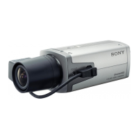
B 2x5
Flexible flat cable
Front cover assembly
Solder
Lead wire
CN401
Portion A
F-2001 board
1-3-2. Front Cover Assembly
For SSC-M183/M183CE/M188CE/M383/M383CE/
M388CE
1. Remove the top cover. (Refer to Section 1-3-1.)
2. Remove the two screws.
3. Move portion A of the front cover assembly in the
direction indicated by the arrow, then remove the front
cover assembly.
4. Disconnect one flexible flat cable from the connector
(CN401) on the F-2001 board.
5. Remove one solder from the F-2001 board, then
disconnect one lead wire.
6. Attach the front cover assembly in the reverse order of
steps 1 to 5.
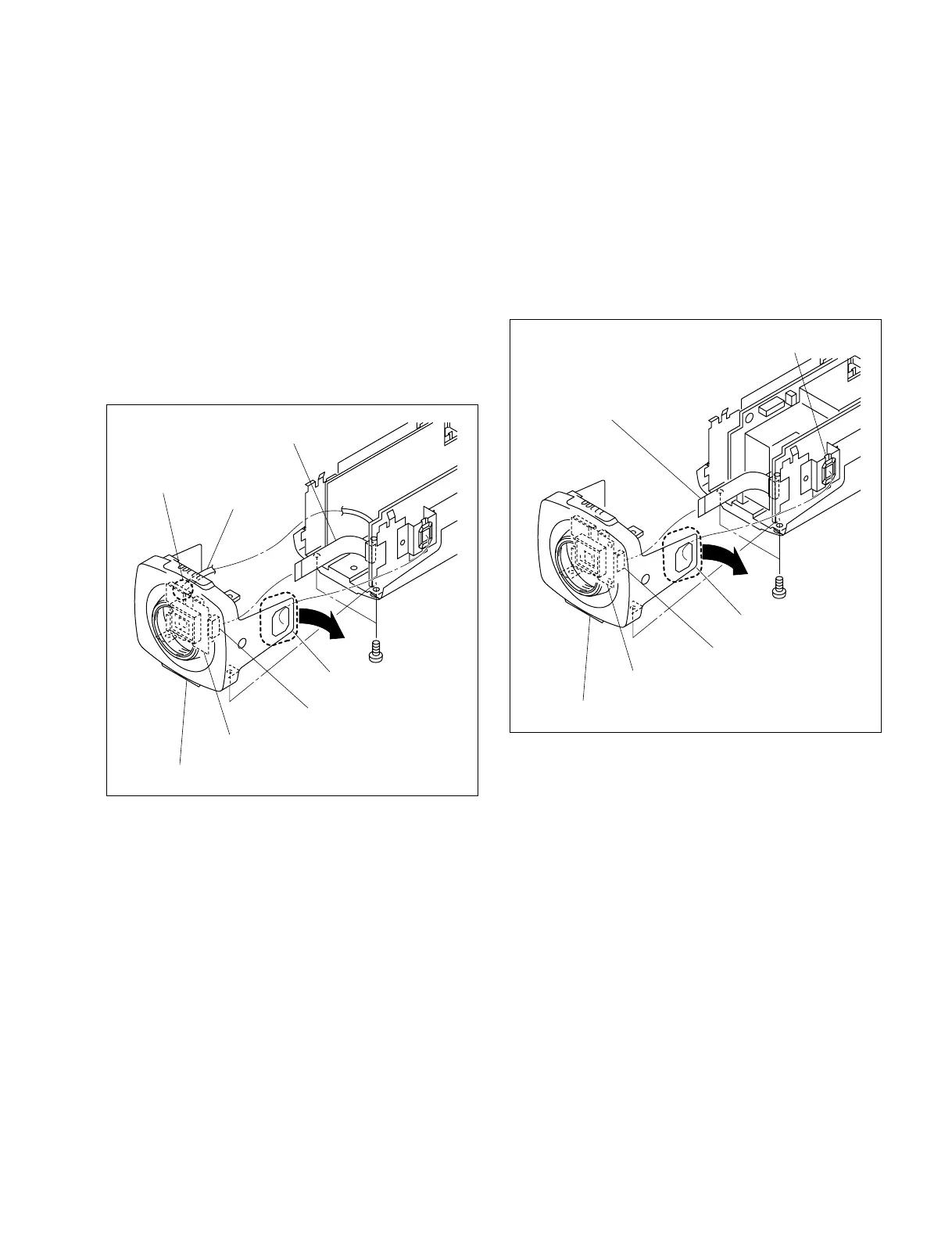
B 2x5
Lens connector
Flexible flat cable
Front cover assembly
Portion A
F-2001 board
CN401
For SSC-DC193/DC193P/DC198P/DC393/DC393P/
DC398P
1. Remove the top cover. (Refer to Section 1-3-1.)
2. Remove the two screws.
3. Move portion A of the front cover assembly in the
direction indicated by the arrow, then remove the front
cover assembly.
4. Disconnect one flexible flat cable from the connector
(CN401) on the F-2001 board.
5. Attach the front cover assembly in the reverse order of
steps 1 to 4.
1-3-3. Bottom Cover
n
Be sure to attach the plate reinforcement in place.
For details on the installation of the plate reinforcement,
refer to Section 1-6.
For SSC-M183/M183CE/M383/M383CE/DC193/
DC193P/DC393/DC393P
1. Remove the top cover. (Refer to Section 1-3-1.)
2. Remove the front cover assembly. (Refer to Section 1-
3-2.)
3. Remove the two screws (B 2x5), then remove the rear
chassis assembly.
 Loading...