EasyManua.ls Logo

Sony STR-DA3000ES User Manual

Sony STR-DA3000ES
168 pages
To Next Page IconTo Next Page
Page #1 background imageLoading...
Page #1 background image
SERVICE MANUAL
This receiver incorporates Dolby* Digital and Pro
Logic Surround and the DTS** Digital Surround
System.
*Manufactured under license from Dolby
Laboratories.
“Dolby”, “Pro Logic” and the double-D symbol are
trademarks of Dolby Laboratories.
** “DTS”, “DTS-ES Extended Surround”, and
“Neo:6” are trademarks of Digital Theater Systems,
Inc.
AUDIO POWER SPECIFICATIONS
POWER OUTPUT AND TOTAL HARMONIC
DISTORTION:
(Models of area code US only)
With 8 ohm loads, both channels driven, from 20
– 20,000 Hz; rated 150 watts per channel
minimum RMS power, with no more than 0.6%
total harmonic distortion from 250 milliwatts to
rated output.
Amplifier section
Models of area code US, Canadian, Taiwan:
POWER OUTPUT
Rated Power Output at Stereo Mode
1)
(8 ohms 20 Hz – 20 kHz, THD 0.6%)
150 W + 150 W
Reference Power Output at Stereo Mode
(4 ohms 20 Hz – 20 kHz, THD 0.6%)
130 W + 130 W
Reference Power Output
(8 ohms 20 Hz – 20 kHz, THD 0.6%)
FRONT
2)
: 150 W + 150 W
CENTER
2)
: 150 W
SURR
2)
: 150 W + 150 W
SURR BACK
2)3)
: 150 W +
150 W
SURR BACK
2)4)
: 150 W
(4 ohms 20 Hz – 20 kHz, THD 0.6%)
FRONT
2)
: 130 W + 130 W
CENTER
2)
: 130 W
SURR
2)
: 130 W + 130 W
SURR BACK
2)3)
: 130 W +
130 W
SURR BACK
2)4)
: 130 W
Models of area code AEP, Korean:
POWER OUTPUT
Rated Power Output at Stereo Mode
1)
(8 ohms 1 kHz, THD 0.7%)
150 W + 150 W
Reference Power Output at Stereo Mode
(4 ohms 1 kHz, THD 0.7%)
130 W + 130 W
Reference Power Output
(8 ohms 1 kHz, THD 0.7%)
FRONT
2)
: 150 W + 150 W
CENTER
2)
: 150 W
SURR
2)
: 150 W + 150 W
SURR BACK
2)
: 150 W
(4 ohms 1 kHz, THD 0.7%)
FRONT
2)
: 130 W + 130 W
CENTER
2)
: 130 W
SURR
2)
: 130 W + 130 W
SURR BACK
2)
: 130 W
1) Depending on the sound field settings and the
source, there may be no sound output.
2) Measured under the following conditions:
3) Models of area code US, Canadian only.
4) Models of area code Taiwan only.
Frequency response
Area code Power requirements
US, Canadian 120 V AC, 60 Hz
Taiwan 110 V AC, 60 Hz
AEP 230 V AC, 50/60 Hz
Korean 220 V AC, 60 Hz
PHONO RIAA equalization curve
±0.5 dB
MULTI CHANNEL
INPUT 1, 2, CD/
SACD, TAPE, MD/
DAT, DVD, TV/SAT,
VIDEO 1, 2, 3
10 Hz – 40 kHz
±3 dB (when sound field and
equalizer bypassed)
FM STEREO FM/AM RECEIVER
SPECIFICATIONS
STR-DA3000ES
Ver 1.1 2004.09
9-961-109-02 Sony Corporation
2004I05-1 Audio Group
© 2004.09 Published by Sony Engineering Corporation
US Model
Canadian Model
AEP Model
E Model
– Continued on next page –

Table of Contents

Other manuals for Sony STR-DA3000ES

Question and Answer IconNeed help?

Do you have a question about the Sony STR-DA3000ES and is the answer not in the manual?

Sony STR-DA3000ES Specifications

General IconGeneral
TypeAV receiver
Channels7.1
Total Harmonic Distortion0.09%
HDMI Outputs1
Component Video Outputs1
Composite Video Inputs4
Digital inputs3 Optical, 1 Coaxial
Digital Audio (Optical) Outputs1
Network ConnectivityNo
Wireless ConnectivityNo
Weight16kg
Frequency Response10Hz to 100kHz
Speaker load impedance8 ohms
Audio Formats SupportedDolby Digital, DTS, Dolby Pro Logic II
Dimensions (W x H x D)430 x 185 x 380 mm

Summary

Sony STR-DA3000ES Service Manual

Audio Power Specifications

Details on power output and total harmonic distortion for various loads and frequency ranges.

Receiver Specifications

Covers power requirements, frequency response, and area code specific details.

Receiver Specifications

FM Tuner Specifications

Details on tuning range, antenna, sensitivity, S/N, distortion, separation, and frequency response.

AM Tuner Specifications

Details on tuning range, antenna, sensitivity, S/N, distortion, and selectivity.

General Unit Specifications

Covers power requirements, power consumption, dimensions, and mass.

SERVICE MANUAL

Safety Checks and Leakage Test

Procedures for safety checks, including AC leakage testing after service.

Unleaded Solder Information

Information regarding the use and characteristics of unleaded solder, including LF mark.

Servicing Notes

Model Identification

Part numbers for different regional models (US, Canadian, AEP, Taiwan, Korean).

Troubleshooting Error Messages

Table listing error codes, causes, and recommended responses for malfunctions.

General Information

Front Panel Controls Location

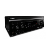
Diagrams and labels identifying controls and connectors on the front panel of the main unit.

Disassembly Procedures

Disassembly Flowchart

Step-by-step guide outlining the sequence for disassembling the set.

Case Disassembly

Procedure for removing the unit's outer case, noting screw types.

Test Modes

Tuner Factory Preset Mode

Resets all tuner preset contents to default settings.

Sound Field Clear Mode

Clears preset sound fields, used before returning product to client.

All Clear Mode

Clears all preset contents, used before returning product to client.

Fluorescent Indicator Tube Pattern Check Mode

Tests all fluorescent segments by turning them on sequentially.

Electrical Adjustments

DC Offset Adjustment

Procedure to adjust DC offset on the D-AMP and REG boards to ±20 mV.

OSD Adjustment

OSD Adjustment

Adjusts NTSC and PAL color system frequencies and settings.

Up Convert Signal Level Adjustment

Up Convert Signal Level Adjustment

Adjusts Y, Color, and Hue levels for up-converted signals using test patterns.

Diagrams and Block Diagrams

Block Diagram: Audio Input Section

Illustrates the signal path for audio inputs, including buffers and input selectors.

Notes on Diagrams and Circuit Boards

Printed Wiring Board Notes

Explains symbols and notations used in printed wiring board diagrams.

Schematic Diagram Notes

Explains notations for capacitors, resistors, signal paths, and abbreviations.

Circuit Board Locations

Diagram showing the physical locations of various boards within the set.

Exploded Views

Exploded View: Case Section

Exploded view of the unit's case, showing chassis and front panel components.

Electrical Parts List: Analog Sub Board

Analog Sub Board Capacitors

List of capacitors used on the ANALOG SUB board, with part numbers and specifications.

Analog Sub Board Connectors

List of connectors used on the ANALOG SUB board.

Analog Sub Board ICs

List of integrated circuits used on the ANALOG SUB board.

Analog Sub Board Resistors

List of resistors used on the ANALOG SUB board, with part numbers and specifications.

Special Menu Mode Procedures

Protector On/Off Setting

Controls the protector function, allowing ON or OFF status.

Model and Destination Change

Allows changing the model and destination settings (XX: at or fx).

DSP Reset Function

Resets the DSP, allowing ON or OFF control.

Bass Management Setup

Configures bass management settings, including AUTO/OFF and zone volume values.

Revision History

Revision History

Details the versions and changes made to the service manual.

Related product manuals