EasyManua.ls Logo

Sony STR-DA3200ES Service Manual

Sony STR-DA3200ES
168 pages
To Next Page IconTo Next Page
Page #1 background imageLoading...
Page #1 background image
SERVICE MANUAL
AUDIO POWER
SPECIFICATIONS (US, Canadian models)
POWER OUTPUT AND TOTAL
HARMONIC DISTORTION:
With 8 ohm loads, both channels driven, from
20 – 20,000 Hz; rated 120 watts per channel
minimum RMS power, with no more than
0.09% total harmonic distortion from 250
milliwatts to rated output.
Amplifier section (US, Canadian models)
POWER OUTPUT
Rated Power Output at Stereo Mode
1) 2)
(8 ohms 20 Hz – 20 kHz,
THD 0.09%):
120 W + 120 W
Reference Power Output at Stereo Mode
2)
(4 ohms 20 Hz – 20 kHz,
THD 0.15%):
120 W + 120 W
Reference Power Output
(8 ohms 1 kHz, THD 0.7%)
FRONT
2)
:
130 W + 130 W
CENTER
2)
:
130 W
SURROUND
2)
:
130 W + 130 W
SURROUND BACK
2)
:
130 W + 130 W
Reference Power Output
(4 ohms 1 kHz, THD 0.7%)
FRONT
2)
:
130 W + 130 W
CENTER
2)
:
130 W
SURROUND
2)
:
130 W + 130 W
SURROUND BACK
2)
:
130 W + 130 W
1)
Depending on the sound field settings and the
source, there may be no sound output.
2)
Measured under the following conditions:
Power requirements: 120 V AC, 60 Hz
Reference Power Output
(8 ohms 20 Hz – 20 kHz,
THD 0.09%)
FRONT
2)
:
120 W + 120 W
CENTER
2)
:
120 W
SURROUND
2)
:
120 W + 120 W
SURROUND BACK
2)
:
120 W + 120 W
Reference Power Output
(4 ohms 20 Hz – 20 kHz,
THD 0.15%)
FRONT
2)
:
120 W + 120 W
CENTER
2)
:
120 W
SURROUND
2)
:
120 W + 120 W
SURROUND BACK
2)
:
120 W + 120 W
Reference Power Output at Stereo Mode
(8 ohms 1 kHz, THD
10%):
150 W + 150 W
Reference Power Output at Stereo Mode
(4 ohms 1 kHz, THD
10%):
150 W + 150 W
Frequency response
PHONO RIAA equalization curve
± 0.5 dB
MULTI CHANNEL
INPUT, SA-CD/CD,
TAPE/C D-R,
MD/DAT, DVD,
VIDEO 1/2/3
10 Hz – 100 kHz
± 3 dB
Reference Power Output
(8 ohms 1 kHz, THD 10%)
FRONT
2)
:
150 W + 150 W
CENTER
2)
:
150 W
SURROUND
2)
:
150 W + 150 W
SURROUND BACK
2)
:
150 W + 150 W
Reference Power Output
(4 ohms 1 kHz, THD 10%)
1)
Depending on the sound field settings and the
source, there may be no sound output.
2)
Measured under the following conditions:
Power requirements: 230 V AC, 50/60 Hz
(in countries/area in Europe
other than the UK)
240 V AC, 50/60 Hz
(in the UK and general area)
Amplifier section (AEP, UK, Taiwan models)
POWER OUTPUT
Rated Power Output at Stereo Mode
1) 2)
(8 ohms 1 kHz, THD
0.7%):
125 W + 125 W
Inputs (Analog)
Inputs (Digital)
PHONO Sensitivity: 2.5 mV
Impedance: 50 kohms
S/N: 86 dB (A, 20 kHz
LPF)
MULTI CHANNEL
INPUT, SA-CD/CD,
TAPE/C D-R , MD/DAT,
DVD, TV/SAT,
VIDEO1/2/3
Sensitivity: 150 mV
Impedance: 50 kohms
S/N: 96 dB (A, 20 kHz
LPF)
DVD, TAPE/CD-R, SA-
CD/CD (Coaxial)
Impedance: 75 ohms
S/N: 96 dB (A, 20 kHz
LPF)
VIDEO 1/2/3, TV/SAT,
MD/DAT (Optical)
S/N: 96 dB
(A, 20 kHz LPF)
Reference Power Output at Stereo Mode
2)
(4 ohms 1 kHz, THD
0.7%):
125 W + 125 W
SURROUND
2)
:
150 W + 150 W
SURROUND BACK
2)
:
150 W + 150 W
CENTER
2)
:
150 W
FRONT
2)
:
150 W + 150 W
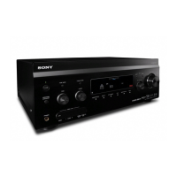
MULTI CHANNEL AV RECEIVER
SPECIFICATIONS
STR-DA3200ES/DG1000
Ver. 1.0 2006.09
– Continued on next page –
9-887-378-01
2006I05-1
© 2006.09
Sony Corporation
Home Audio Division
Published by Sony Techno Create Corporation
US Model
STR-DA3200ES/DG1000
Canadian Model
AEP Model
UK Model
Taiwan Model
STR-DA3200ES
This receiver incorporates Dolby* Digital and Pro Logic Surround and the DTS** Digital Surround System.
*Manufactured under license from Dolby Laboratories.
“Dolby”, “Pro Logic”, “Surround EX”, and the double-D symbol are trademarks of Dolby Laboratories.
** Manufactured under license from Digital Theater Systems, Inc. U.S. Pat.
No’s. 5,451,942; 5,956,674; 5,974,380; 5,978,762; 6,226,616; 6,487,535 and other U.S.
and world-wide patents issued and pending.
“DTS”, “DTS-ES”, “Neo:6”, and “DTS 96/24” are trademarks of Digital Theater Systems, Inc.
Copyright 1996, 2003 Digital Theater Systems, Inc. All Rights Reserved.
Photo: STR-DA3200ES

Table of Contents

Other manuals for Sony STR-DA3200ES

Question and Answer IconNeed help?

Do you have a question about the Sony STR-DA3200ES and is the answer not in the manual?

Sony STR-DA3200ES Specifications

Audio IconAudio
impedance8 Ohm
channel power rating120 Watts X 7 Amp
zones2 Zone/2 Room
Inputs and Outputs IconInputs and Outputs
s-video outputs1 (Rear)
composite video outputs3 (Rear)
optical audio outputs1 (Rear)
Power IconPower
power requirementsAC 120V, 60 Hz
power consumption (in operation)TBD
power consumption (in standby)TBD
Weight and Dimensions IconWeight and Dimensions
weight34 lbs 3oz (15.5kg)
measurements17" x 7" x 17" (430mm x 175mm x 430mm)
colorBlack

Summary

Audio Specifications

Power Output and Distortion

Specifies power output and harmonic distortion for various models and channels.

General and Output Specifications

Safety Check-out Procedures

Essential safety checks including AC leakage testing after repairs.

Servicing Notes and Procedures

Board Service Positions and Disassembly

General Controls and Connections

Disassembly Procedures

Disassembly Flowchart

Visual guide outlining the sequence for disassembling the unit.

Test Modes

Electrical Adjustments

Bias Alignment Adjustment Procedure

Step-by-step guide for adjusting bias alignment on the BIAS board.

OSD Adjustment Procedure

Procedure for adjusting OSD color system frequency settings.

Up Convert Signal Level Adjustments

Diagrams Overview

Block Diagrams

Illustrates functional blocks and signal paths for Control, DSP, HDMI, Analog Audio sections.

Block Diagram - Electrical Volume and Power Amp

Block Diagram - Video and Display Sections

Block Diagram - Power Supply Section

Schematic Diagram - Digital Board (1/5)

Printed Wiring Board - Digital Board (Component Side)

Printed Wiring Board - DSP Board

Printed Wiring Board - HDMI Board (Component Side)

Schematic Diagram - HDMI Board (1/6)

Printed Wiring Board - XM Board

Schematic Diagram - XM Board

Printed Wiring Board - CIS Board

Schematic Diagram - CIS Board

Printed Wiring Board - Analog Board

Schematic Diagram - Analog Board

Waveform Diagrams

Printed Wiring Board - Main Board

Schematic Diagram - Main Board (1/2)

Schematic Diagram - Main Board (2/2)

Printed Wiring Board - E-Volume Board

Schematic Diagram - E-Volume Board

Printed Wiring Board - A Class Amp Board

Schematic Diagram - A Class Amp Board

Printed Wiring Board - Power Amp Board

Schematic Diagram - Power Amp Board

Printed Wiring Board - Bias Board

Schematic Diagram - Bias Board

Printed Wiring Board - Video Board

Schematic Diagram - Video Board (1/3)

Schematic Diagram - Video Board (2/3)

Schematic Diagram - Video Board (3/3)

Printed Wiring Board - S-Video Board

Schematic Diagram - S-Video Board

Printed Wiring Board - Video 3 Board

Schematic Diagram - Video 3 Board

Printed Wiring Board - Display Board

Schematic Diagram - Display Board

Printed Wiring Boards - Key Section

Schematic Diagram - Key Section

Printed Wiring Boards - Speaker Section

Printed Wiring Boards - DC and Power SW Sections

Printed Wiring Board - AC Board

Schematic Diagram - Power Supply Section

Digital Board IC Diagrams

IC Pin Function Descriptions

Detailed pinout and function descriptions for ICs on the Digital Board.

Integrated Circuit Pin Function Descriptions

Digital Board IC2054 Pin Functions

Pinout and function description for IC2054 (System Controller).

DSP Board IC2 Pin Functions

HDMI Board IC3509 Pin Functions

HDMI Board IC3509 Pin Functions (Continued)

Continued pinout and function description for IC3509 (HDMI Controller).

HDMI Board IC3516 Pin Functions

XM Board IC3802 Pin Functions

Exploded Views of Unit Components

Electrical Parts List

Related product manuals