2929
STR-DA3200ES/DG1000
STR-DA3200ES/DG1000
UP CONVERT SIGNAL LEVEL ADJUSTMENT
Enter the test mode
1. In the standby status, press the [POWER] button while pressing
the [2CH] and [TONE MODE] buttons.
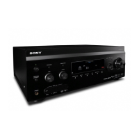
2. It enters the test mode, and display as below figure.
1. Y Level Adjustment
Setting:
Procedure:
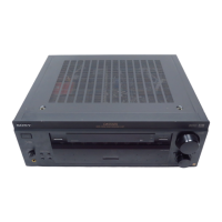
1. Connect a color pattern generator to the DVD S VIDEO IN
jack (J6902) on the S-VIDEO board, and connect an
oscilloscope to the COMPONENT VIDEO MONITOR OUT
Y jack (J6101) on the VIDEO board.
2. Enter the test mode.
3. Input color bars signal from the color pattern generator.
4. Adjust the [TUNING] dial so that the Vp-p value of waveform
becomes 1 Vp-p.
2. Color Level Adjustment
Setting:
Procedure:
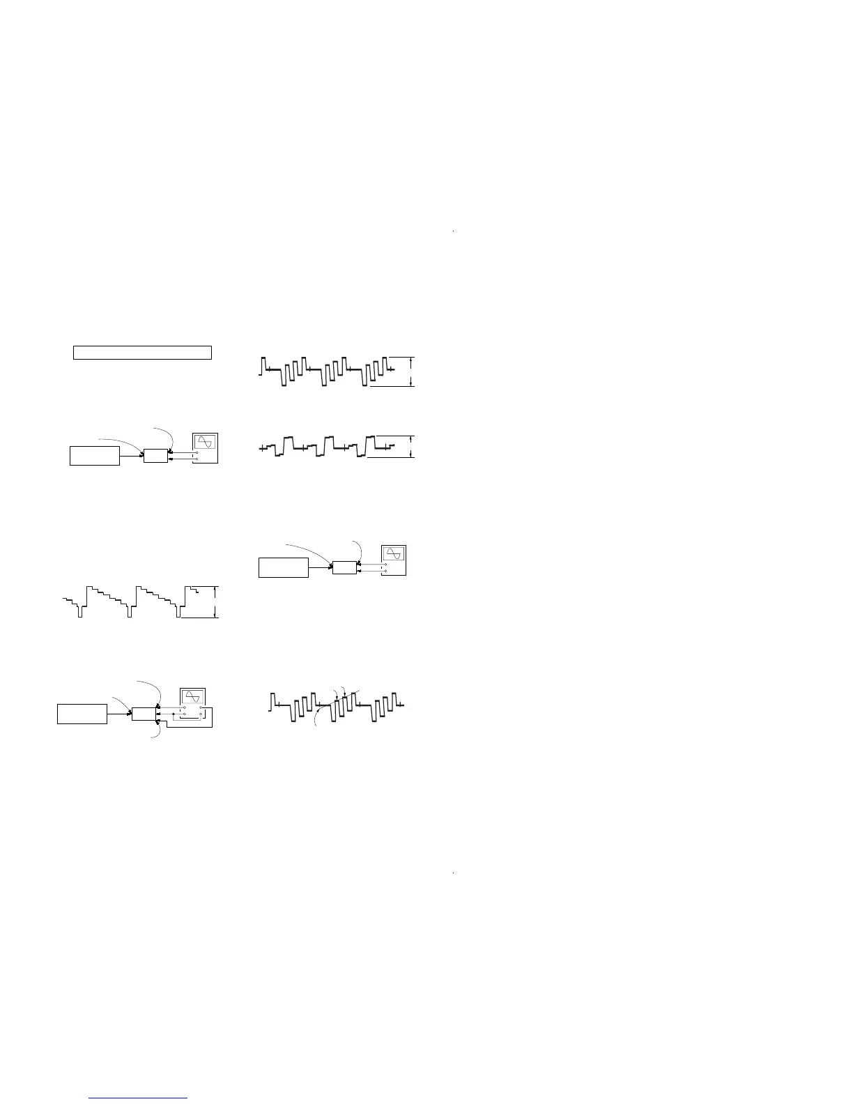
1. Connect a color pattern generator to the DVD S VIDEO IN
jack (J6902) on the S-VIDEO board, and connect an
oscilloscope to the COMPONENT VIDEO MONITOR OUT
P
B
/C
B
jack and COMPONENT VIDEO MONITOR OUT P
R
/
C
R
jack (J6101) on the VIDEO board .
2. Enter the test mode.
3. Input color bars signal from the color pattern generator.
4. Display two waveforms of C
B
and C
R
simultaneously.
5. Adjust the [INPUT SELECTOR] dial so that the Vp-p value of
waveforms of C
B
and C
R
both may be most set to 0.7V closely.
3. HUE Level Adjustment
Setting:
Procedure:
1. Connect a color pattern generator to the DVD S VIDEO IN
jack (J6902) on the S-VIDEO board, and connect an
oscilloscope to the COMPONENT VIDEO MONITOR OUT
P
B
/C
B
jack (J6101) on the VIDEO board.
2. Enter the test mode.
3. Input color bars signal from the color pattern generator.
4. Adjust the [TONE] dial so that the waveform as bellow.
Display
HU[ 7]CON[ 7]COL[ 7]