7
Getting Started
Getting Started
Notes
• This setting is effective only when the receiver is set
to TAPE, DAT/MD, VIDEO 2, or CD (see page 13).
For VIDEO 2, the CD changer command mode must
be “CD 2” and the CD changer must be connected to
the VIDEO 2 jacks on the receiver. For CD, the CD
changer command mode must be “CD 1” and the CD
changer must be connected to the CD jacks on the
receiver.
• If the disc or track memo contains a character that the
receiver cannot display, “.” appears for that character.
• When the Mega Control function of the CD player is
active, the operating status of the main player is
displayed.
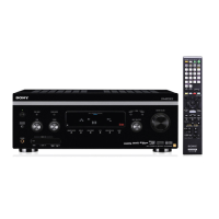
Speaker System Hookups
Overview
This section describes how to connect your speakers to
the receiver. Although front (left and right) speakers
are required, center and rear speakers are optional.
Adding center and rear speakers will enhance the
surround effects. Connecting an active woofer will
increase bass response.
AC OUTLET
IMPEDANCE
SELECTOR
SWITCHED 120W / 1A MAX
4 Ω 8 Ω
AC 120V 60Hz
CTRL A1
IN
FM
75Ω
COAXIAL
S-LINK
FRONT SPEAKERS
+
RLRBAL
–
+
–
IMPEDANCE USE 4–16 Ω
REAR SPEAKERS
+
RL
–
+
–
IMPEDANCE USE 4–16 ΩIMPEDANCE USE 4–16 Ω
CENTER SPEAKER
AM
y
S VIDEO
IN
S VIDEO
IN
OUT
S VIDEO
OUT
S VIDEO
OUT
S VIDEO
IN
S VIDEO
IN
S VIDEO
OUT
VIDEO
IN
VIDEO
OUT
VIDEO
IN
VIDEO
OUT
VIDEO
IN
IN
L
R
L
R
L
R
REC OUT
ININ
AUDIO
IN
REAR
CENTER
WOOFER
FRONT
L
R
AUDIO
OUT
AUDIO
IN
AUDIO
OUT
AUDIO
IN
PHONO
DAT / MD
MONITORVIDEO 1VIDEO 2
LD / DVD
VIDEO
IN
LD
DVD
AC-3 RF IN
AUDIO
IN
TV / DBS
CD
IN
REC OUT
TAPE
SIGNAL
GND
y
LD
DVD
COAXIAL IN
LD
DVD
OPTICAL IN
TV
DBS
OPTICAL IN
CD
OPTICAL IN
DAT
MD
OPTICAL IN
DAT
MD
OPTICAL OUT
ANTENNA
DIGITAL
PRE OUT
PRE OUT REAR
SPEAKERS
CENTER
SPEAKER
IMPEDANCE SELECTOR FRONT SPEAKERS A
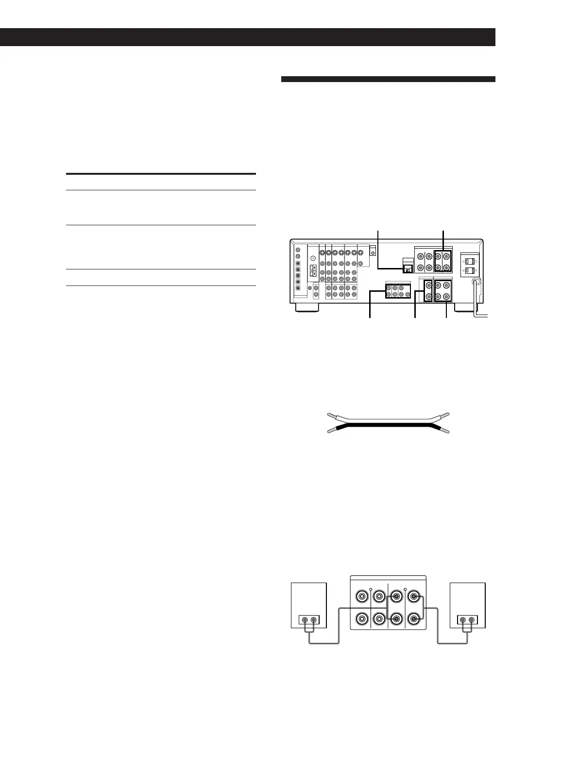
What cords will I need?
Speaker cord (not supplied) (1 for each speaker)
(+) (+)
(–) (–)
Twist the stripped ends of the cord about 2/3 inch (15 mm).
Be sure to match the speaker cord to the appropriate
terminal on the components: + to + and – to –. If the cords
are reversed, the sound will be distorted and will lack bass.
Hookups
Front speakers
]]}}
FRONT SPEAKERS
+
RLR
BA
L
–
+
–
IMPEDANCE USE 4–16 Ω
(Continued)
Front speaker
(R)
Front speaker
(L)
Receiver
z You can display the operating status of the
component connected to the S-LINK CTRL A1 jack
(USA and Canadian models only)
1 Press SET UP repeatedly to select OTHER SETUP.
2 Use the digital processing control buttons ( V / v ) to
select CONTROL-A1.
3 Use the digital processing control buttons ( B / b ) to
select the setting you want by referring to the
following table.
To Select
Display “PLAY,” “STOP,” “PAUSE,”
or “REC” for about 8 seconds when
the operation switches
AUTO
Display “PLAY,” “STOP,” “PAUSE,”
“REC,” or the contents of a disc or
track memo of a CD or MD whenever
you press the DISPLAY button
FIX
Turn off the operation status display OFF