EasyManua.ls Logo

Sony STR-DA5300ES Service Manual

Sony STR-DA5300ES
260 pages
To Next Page IconTo Next Page
Page #1 background imageLoading...
Page #1 background image
SERVICE MANUAL
AUDIO POWER
SPECIFICATIONS (US model)
POWER OUTPUT AND TOTAL
HARMONIC DISTORTION:
With 8 ohm loads, both channels driven, from
20 20,000 Hz; rated 120 watts per channel
minimum RMS power, with no more than
0.09% total harmonic distortion from 250
milliwatts to rated output.
Amplifier section
POWER OUTPUT
(US and Canadian models)
Rated Power Output at Stereo Mode
1) 2)
(8 ohms 20 Hz 20 kHz,
THD 0.09%):
120 W + 120 W
Reference Power Output at Stereo Mode
(4 ohms 20 Hz 20 kHz,
THD 0.15%):
120 W + 120 W
Reference Power Output
(8 ohms 1 kHz, THD 0.7%)
FRONT
2)
:
130 W + 130 W
CENTER
2)
: 130 W
SURROUND
2)
:
130 W + 130 W
SURROUND BACK
2)
:
130 W + 130 W
Reference Power Output
(4 ohms 1 kHz, THD 0.7%)
FRONT
2)
:
120 W + 120 W
CENTER
2)
: 120 W
SURROUND
2)
:
120 W + 120 W
SURROUND BACK
2)
:
120 W + 120 W
1)
Depending on the sound field settings and the
source, there may be no sound output.
2)
Measured under the following conditions:
Power requirements: 120 V AC, 60 Hz
(AEP, Russian, Ukrainian and UK models)
Rated Power Output at Stereo Mode
1) 2)
(8 ohms 1 kHz, THD
0.7%):
125 W + 125 W
Reference Power Output at Stereo Mode
(4 ohms 1 kHz, THD
0.7%):
125 W + 125 W
Reference Power Output
(8 ohms 20 Hz 20 kHz,
THD 0.09%)
FRONT
2)
:
120 W + 120 W
CENTER
2)
: 120 W
SURROUND
2)
:
120 W + 120 W
SURROUND BACK
2)
:
120 W + 120 W
Reference Power Output
(4 ohms 20 Hz 20 kHz,
THD 0.15%)
FRONT
2)
:
120 W + 120 W
CENTER
2)
: 120 W
SURROUND
2)
:
120 W + 120 W
SURROUND BACK
2)
:
120 W + 120 W
Reference Power Output at Stereo Mode
(8 ohms 1 kHz, THD
10%):
150 W + 150 W
MULTI CHANNEL AV RECEIVER
SPECIFICATIONS
Ver. 1.1 2007.10
– Continued on next page –
9-887-741-02
2007J05-1
© 2007.10
Sony Corporation
Home Audio Division
Published by Sony Techno Create Corporation
This receiver incorporates Dolby* Digital and Pro Logic Surround and the DTS** Digital Surround System.
* Manufactured under license from Dolby Laboratories.
Dolby, Pro Logic, Surround EX, and the double-D symbol are trademarks of Dolby Laboratories.
** Manufactured under license from DTS, Inc.
“DTS”, “DTS-ES” and “Neo:6” are registered trademarks of DTS, Inc. and “DTS-HD Master Audio”,
“DTS-HD High Resolution Audio” and “DTS 96/24” are trademarks of DTS, Inc.
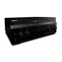
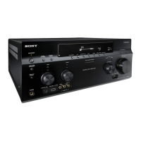
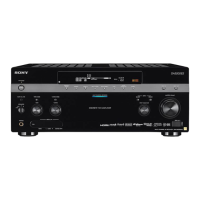
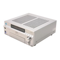
STR-DA5300ES
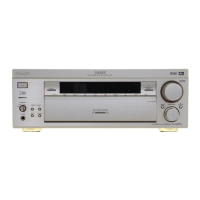
US Model
Canadian Model
AEP Model
UK Model

Table of Contents

Other manuals for Sony STR-DA5300ES

Question and Answer IconNeed help?

Do you have a question about the Sony STR-DA5300ES and is the answer not in the manual?

Sony STR-DA5300ES Specifications

General IconGeneral
EqualizerYes
Product colorBlack
Frequency range20 - 20000 Hz
Audio output channels7.1 channels
Total Harmonic Distortion (THD)0.09 %
Supported radio bandsAM, FM
I/O ports1 x DM-Port 5 x Audio In 2 x Audio Out 5 x A/V In 1 x A/V Out 1 x S-Video 3 x Component Video In 1 x Component Video Out 1 x Multi-ch In 1 x SW 6 x Digital In 1 x Digital Out 6 x HDMI In 1 x HDMI Out 6 x Opt. IN 1 x Opt. Out 3 x Coax.
Connectivity technologyWired
Dimensions (WxDxH)430 x 424.8 x 171.5 mm
HDMI ports quantity7
Weight and Dimensions IconWeight and Dimensions
Weight16000 g

Summary

SERVICE MANUAL

AUDIO POWER SPECIFICATIONS (US model)

Lists power output and total harmonic distortion for US models.

SPECIFICATIONS

Contains detailed technical specifications for the receiver.

Amplifier section POWER OUTPUT

Details power output ratings for various models.

SAFETY-RELATED COMPONENT WARNING!!

SAFETY CHECK-OUT

Procedures for performing safety checks after service.

LEAKAGE TEST

Methods for measuring AC leakage current to ensure safety.

SERVICING NOTES

UNLEADED SOLDER

Information on using unleaded solder and identifying lead-free marks.

NOTE WHEN THE AC BOARD IS REPAIRED

Distinguishing between AC board types for US and Canadian models during repair.

NOTE OF REPLACING THE IC3601 ON THE D-VIDEO BOARD

Special tool required for replacing IC3601 on the D-VIDEO board.

NOTE OF REPLACING THE IC5002 AND IC5202 ON THE DSP BOARD

IC5002 and IC5202 on the DSP board must be exchanged as a single unit.

TEST MODE

MEMORY CLEARING MODE

Clears all preset memory contents and resets to default values.

SOUND FIELD CLEAR MODE

Clears preset sound fields and resets initialization settings.

XM FACTORY TEST MODE (US and Canadian models only)

Confirms XM antenna operation, ID display, and audio signal output.

DIGITAL MEIDA PORT TEST

Tests the DMPORT connection and verifies audio/video signal output.

HISTORY MODE

SPECIAL MENU MODE

ELECTRICAL ADJUSTMENTS

BIAS ALIGNMENT ADJUSTMENT

Procedure for adjusting the bias voltage for amplifier channels.

DIAGRAMS

6-1. BLOCK DIAGRAM – CONTROL Section –

Illustrates the functional blocks and signal paths within the control section.

6-12. BLOCK DIAGRAM – POWER SUPPLY Section –

Illustrates the power supply circuits and voltage distribution to various sections.

• Circuit Boards Location

6-13. PRINTED WIRING BOARD – MAIN Board (Component Side) –

6-14. PRINTED WIRING BOARD – MAIN Board (Conductor Side) –

6-15. SCHEMATIC DIAGRAM – MAIN Board (2/4) –

6-19. PRINTED WIRING BOARD – DIGITAL Board (Component Side) –

6-21. SCHEMATIC DIAGRAM – DIGITAL Board (1/4) –

6-27. SCHEMATIC DIAGRAM – DSP Board (2/4) –

6-31. PRINTED WIRING BOARD – ANALOG Board (Component Side) –

6-33. SCHEMATIC DIAGRAM – ANALOG Board (1/3) –

6-36. PRINTED WIRING BOARD – E-VOL Board –

6-37. SCHEMATIC DIAGRAM – E-VOL Board (1/2) –

6-39. PRINTED WIRING BOARDS – CONNECTOR Section –

7-1. CASE SECTION

7-2. DIGITAL BOARD SECTION

7-3. D-VIDEO BOARD SECTION

7-4. DISPLAY BOARD SECTION

7-5. FRONT PANEL SECTION

7-6. A-VIDEO BOARD SECTION

7-7. ANALOG BOARD SECTION

7-8. HEAT SINK SECTION

7-9. MAIN BOARD SECTION

8. ELECTRICAL PARTS LIST

REVISION HISTORY

1.0 2007.07 New

Initial release of the service manual.

1.1 2007.10 Addition of Russian and Ukrainian models

Updates include models for Russia, Ukraine, and board changes.

Related product manuals