SERVICE MANUAL
STR-DA5300ES
1
STR-DA5300ES
Ver. 1.1 2007.10
Subject: Change of CONTROL board
(Combined Suffix-13/-14)
Change of DIGITAL board
(Combined Suffix-12/-13/-14)
Change of DSP board (Combined Suffix-12)
9-887-741-81
SUPPLEMENT-1
File this supplement with the service manual.
STR-DA5300ES
US Model
Canadian Model
AEP Model
UK Model
In this set, CONTROL, DIGITAL and DSP boards have been changed in
the midway of production.
Printed wiring board, schematic diagram and electrical parts list of new
type are described in this supplement-1.
Refer to original service manual for other information.
1. NEW/FORMER DISCRIMINATION ................... 1
2. DIAGRAMS
2-1. Printed Wiring Board – DIGITAL Board
(Component Side) (Suffix-12/-13) – ............................... 3
2-2. Printed Wiring Board – DIGITAL Board
(Conductor Side) (Suffix-12/-13) – ................................. 4
2-3. Printed Wiring Board – DIGITAL Board
(Component Side) (Suffix-14) –...................................... 5
2-4. Printed Wiring Board – DIGITAL Board
(Conductor Side) (Suffix-14) – ....................................... 6
2-5. Schematic Diagram – DIGITAL Board (1/4) – ............... 7
2-6. Schematic Diagram – DIGITAL Board (2/4) – ............... 8
2-7. Schematic Diagram – DIGITAL Board (3/4) – ............... 9
2-8. Schematic Diagram – DIGITAL Board (4/4) – ............... 10
2-9. Printed Wiring Board – DSP Board (Side A) – ............... 11
2-10. Printed Wiring Board – DSP Board (Side B) – ............... 12
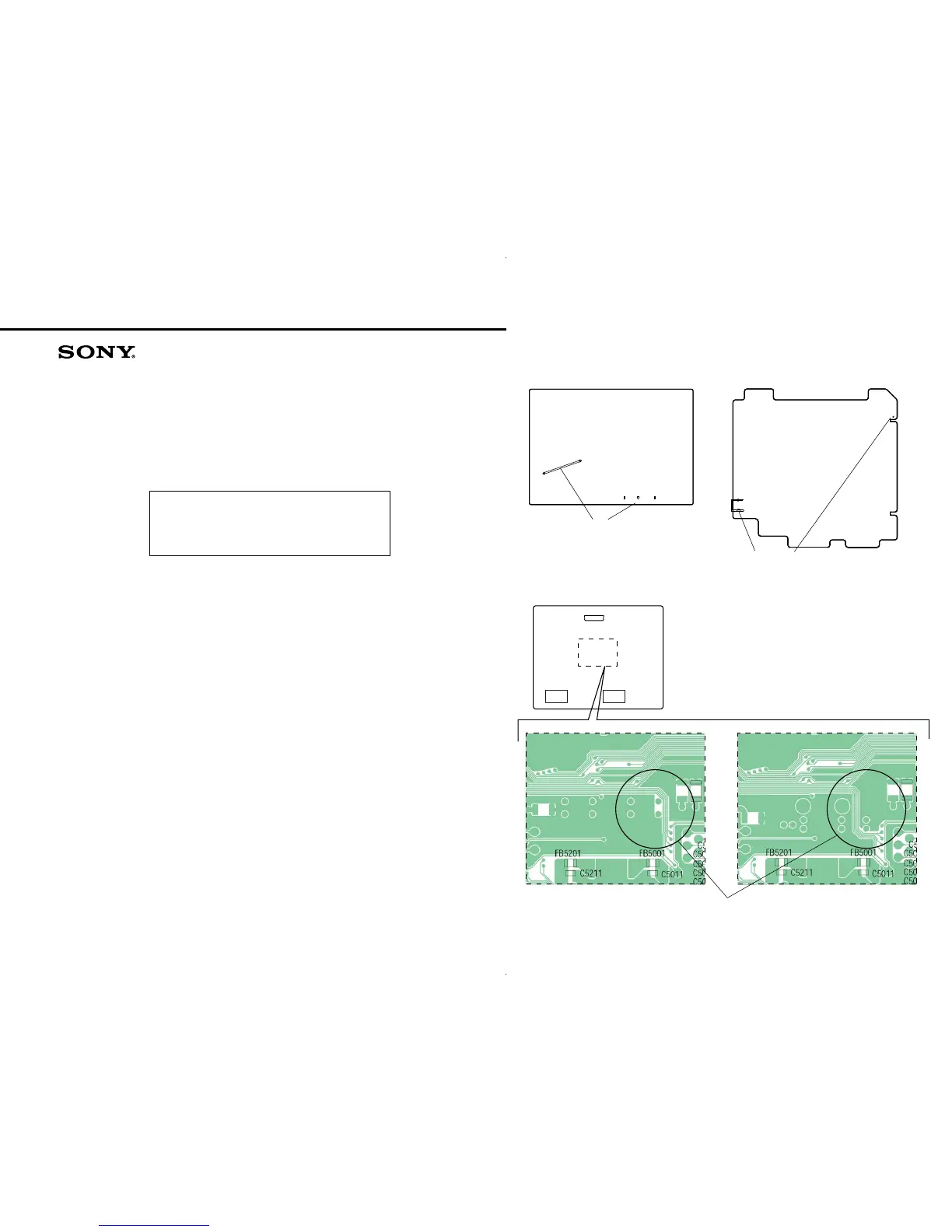
1. NEW/FORMER DISCRIMINATION
Note: CONTROL and DIGITAL boards of Russian and Ukrainian models
uses only Suffix-14.
– DIGITAL Board (Component Side) –
– CONTROL Board (Component Side) –
JW2201
A2002
Hole
R2503 R2501
R2502
Suffix-11 : JW2201 is not mounted, and
R2501 to R2503 are not mounted.
Suffix-12/-13 : JW2201 is not mounted, and
R2501 to R2503 are mounted.
Suffix-14 : JW2201 is mounted, and
R2501 to R2503 are mounted.
Suffix-11/-12 : Hole is not open, and A2002 is not mounted.
Suffix-13 : Hole is open, and A2002 is not mounted.
Suffix-14 : Hole is open, and A2002 is mounted.
IC5007
IC5008
IC5001
Suffix-12
Suffix-11
pattern is different.
– DSP Board (Side B) –
TABLE OF CONTENTS
2-11. Schematic Diagram – DSP Board (1/4) – ....................... 13
2-12. Schematic Diagram – DSP Board (2/4) – ....................... 14
2-13. Schematic Diagram – DSP Board (3/4) – ....................... 15
2-14. Schematic Diagram – DSP Board (4/4) – ....................... 16
2-15. Printed Wiring Board – CONTROL Board
(Component Side) (Suffix-13) –...................................... 17
2-16. Printed Wiring Board – CONTROL Board
(Conductor Side) (Suffix-13) – ....................................... 18
2-17. Printed Wiring Board – CONTROL Board
(Component Side) (Suffix-14) –...................................... 19
2-18. Printed Wiring Board – CONTROL Board
(Conductor Side) (Suffix-14) – ....................................... 20
2-19. Schematic Diagram – CONTROL Board (1/2) – ............ 21
2-20. Schematic Diagram – CONTROL Board (2/2) – ............ 22
3. ELECTRICAL PARTS LIST................................ 23