30
STR-DA5300ES
SECTION 5
ELECTRICAL ADJUSTMENTS
BIAS ALIGNMENT ADJUSTMENT
Note: Afer 10 minutes or more have passed since the power supply was
turned on, this adjustment is done.
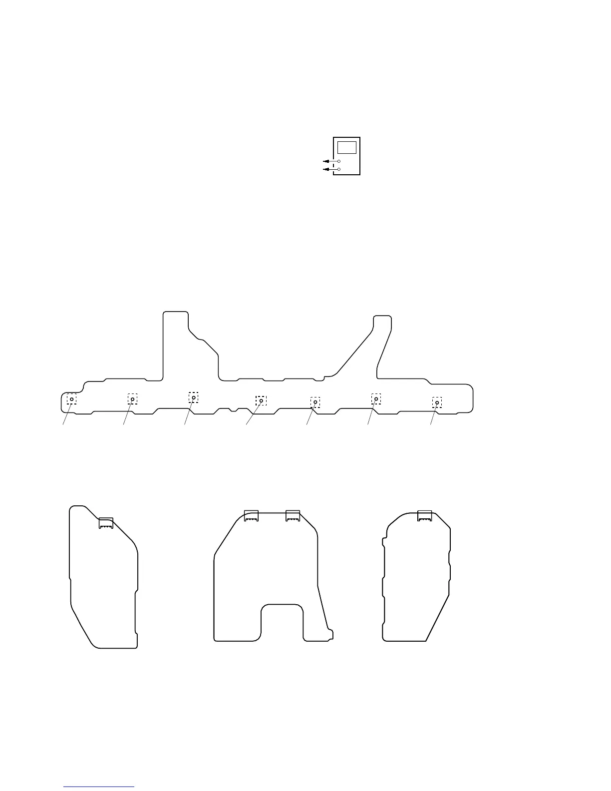
Connection:
Note: Pin 3, 4 of CN1611 are open.
Procedure:
1. Connect a digital voltmeter to the CN1561 (CN1611, CN1761,
CN1861).
2. Press the [POWER] button to turn on the main power.
3. Adjust the RV1501 (RV1551, RV1601, RV1701, RV1751,
RV1801, RV1851) so that the digital voltmeter reading is 5 mV
to 20 mV.
Adjustment and Connection Location:
+
–
digital voltmeter
CN1561 (CN1611, CN1761, CN1861) pin
1
, CN1561 (CN1761, CN1861) pin
3
CN1561 (CN1611, CN1761, CN1861) pin
2
, CN1561 (CN1761, CN1861) pin
4
Adjustment hole
for RV1801
(SBL)
– BIAS Board (Conductor Side) –
– PROTECTOR (F-C) Board
(Component Side) –
– PROTECTOR (SURR) Board
(Component Side) –
– PROTECTOR (SB) Board
(Component Side) –
4
1
CN1561
4
1
CN1761
4
1
CN1611
4
1
CN1861
Adjustment hole
for RV1851
(SBR)
Adjustment hole
for RV1601
(CENTER)
Adjustment hole
for RV1501
(F-L)
Adjustment hole
for RV1551
(F-R)
Adjustment hole
for RV1701
(SUR-L)
Adjustment hole
for RV1751
(SUR-R)