Do you have a question about the Sony STR-DA5400ES and is the answer not in the manual?
Perform safety checks after service to ensure AC leakage is within limits.
List of error codes displayed by the unit, with their causes and recommended actions.
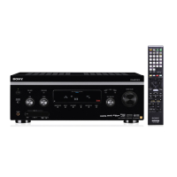
Details the functions of buttons, jacks, and display elements on the front panel.
Step-by-step guide for disassembling the set, indicating the order of component removal.
Procedure for removing the outer case of the receiver for access to internal components.
Instructions for accessing and disassembling the power transformer and E-VOL/MAIN boards.
Procedure for testing the DMPORT connection and communication.
Mode to confirm operation of XM antenna, ID, and audio signal transmission.
Mode to confirm operation of SIRIUS antenna, ID, and audio signal transmission.
Accesses special diagnostic menus for system version, factory settings, and calibration.
Procedure for adjusting the bias alignment of amplifier stages to specified voltage levels.
Procedure to set the standard of video input signals, including NTSC, PAL, and HD.
High-level overview of the receiver's internal circuitry and signal flow.
Component layout and placement diagrams for various circuit boards.
Detailed electrical schematics showing circuit connections for each board.
Detailed pinout and function descriptions for integrated circuits used in the receiver.
Exploded view of the receiver's case and related external parts.
Exploded view showing the digital board and its related components and connectors.
Exploded view showing the D VIDEO board and its related components and connectors.
Exploded view showing the display board and its related components and connectors.
Exploded view of the front panel assembly, including buttons, displays, and connectors.
Exploded view showing the A-VIDEO board and its related components.
Exploded view showing the analog board and its related components.
Exploded view detailing the heat sink assembly and related components.
Exploded view illustrating the main board and its primary components.
List of all capacitors used in the unit, with part numbers, descriptions, and specifications.
List of all connectors used in the unit, with part numbers and terminal descriptions.
List of all diodes used in the unit, with part numbers and descriptions.
List of all integrated circuits used in the unit, with part numbers and descriptions.
List of all resistors used in the unit, with part numbers, descriptions, and specifications.
List of all transistors used in the unit, with part numbers and descriptions.
| Equalizer | Yes |
|---|---|
| Product color | Black |
| Frequency range | 20 - 20000 Hz |
| Audio output channels | 7.1 channels |
| Total Harmonic Distortion (THD) | 0.09 % |
| Supported radio bands | AM, FM |
| I/O ports | 1 x AV 2 x DM-Port 5 x Audio In 2 x Audio Out 5 x A/V In 1 x A/V Out 1 x S-Video 3 x Component Video In 1 x Component Video Out 1 x Multi-ch In 1 x SW 6 x Digital In 1 x Digital Out 6 x HDMI In 2 x HDMI Out 6 x Opt. IN 1 x Opt. Out 3 x Coax. |
| Connectivity technology | Wired |
| Dimensions (WxDxH) | 430 x 430 x 175 mm |
| Power requirements | 230V, 50/60Hz |
| HDMI ports quantity | 8 |
| Package weight | 21000 g |
| Power consumption (standby) | 0.9 W |
| Power consumption (typical) | 480 W |
| Weight | 16500 g |
|---|