28
STR-DA5300ES
SPECIAL MENU MODE
Procedure:
1. Press the [POWER] button to turn on the main power, then while pressing the [TONE MODE] button, press the [A.F.D.], [2CH/A. DIRECT],
[MUSIC], [MOVIE] button in order, the message “MENU SPECIALIZED!” appears.
2. Press the M m button of the remote commander, the message “<<< SPECIAL >>>” appears.
3. Press the , button of the remote commander, the item is appears.
4. Each time the M m button of the remote commander is pressed, the item is switched in order as follows.
Some items can change the content. Display the cursor by pressing the , button of the remote commander, and changing the content
by pressing the M m button of the remote commander, and fix the content by pressing the < button of the remote commander when
you want to change the content of the item.
5. To release from this mode, while pressing the [TONE MODE] button, press the [A.F.D.], [2CH/A. DIRECT], [MUSIC], [MOVIE] button in
order again, the message “MENU SPECIALIZED OFF” appears.
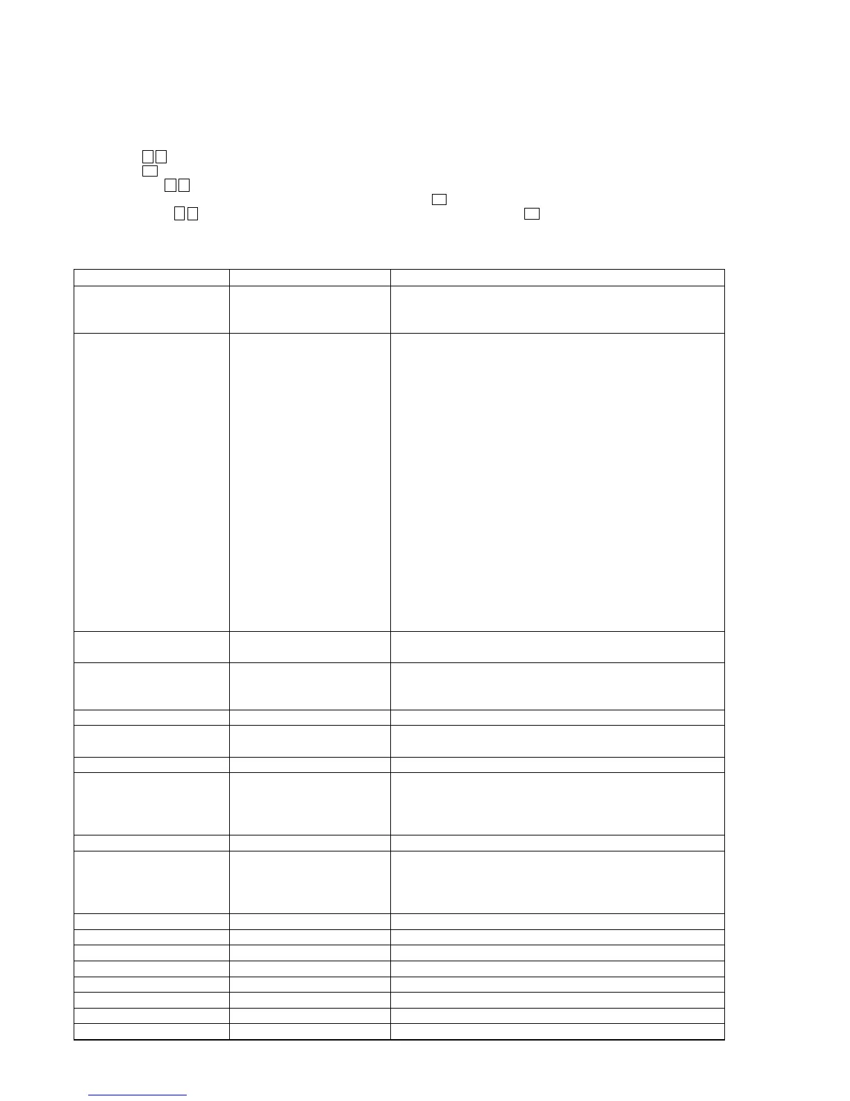
Items Display Remark
Video factory menu <VIDEO FACTORY MENU> Menu mode to enter video calibration menu and DDR access check menu
If the [ENTER] button of the remote commander is pressed, entering the
menu, and operating two the following menu become possible
Video calibration V.CALIBRATION START? Procedure:
(Video factory menu) 1. “DVD” is selected by using [INPUT SELECTOR] dial.
2. Connect a color pattern generator to the COMPONENT VIDEO
ASSIGNABLE (INPUT ONLY) DVD/BD IN jack (J6002) on the A-
VIDEO board, DVD/BD VIDEO IN jack (J6201) on the A-VIDEO
board, DVD/BD S VIDEO IN jack (J6901) on the S-VIDEO board and
EXT VIDEO IN jack (J6904).
3. Input 100% color bars signal from the color pattern generator.
4. Menu that measures individual difference of hardness by automatic
operation in pressing the [ENTER] button of the remote commander, and
corrects reference value.
In a measurement once, only one of NTSC/PAL/HD can be measured
“Check XXXX V-IN” at display:
Video signal necessary for the measurement while measuring it last time
was not detected and it became an error
Confirm the input of the video of the terminal connection etc. , and
measure the [ENTER] button of the remote commander again pressing
DDR access check DDR CHECK [XX] sec XX: Time to do access check on DDR (for design evaluation)
(Video factory menu)
Auto cal mic test SPEAKER OUT [XXXXX] XXXXX: Selection of speaker output audio
[SOURCE]: nomally mode, [MIC]: mode that output audio from mic from
speaker
FL display fonts test FL FONT [0x ** = X] **: 20 to FE, X: character
FL display test ALL ON Each time DISPLAY button to change as follows
all on t test pattern 1 t test pattern 2 t all off t all on
HDCP key read HDCP KEY READ [XXX] XXX: ON or OFF
DSP SRAM check <DSP SRAM CHECK> XX: OK or NG
r
[ENTER] button of the remote OK: success access SRAM, NG: fail access to SRAM
commander
SRAM1 [XX] SRAM2 [XX]
FAROUDJA update FAROUDJA UPDATE [XXX] XXX: ON or OFF
Model version display ##### *** vX. XX @@@@ #####: Model
***: Destination
X.XX: System controller software version
@@@@: Sum value of flash memory in the system controller
Video Ucom version display Video Ucom Ver X. XX X.XX: Video system controller software version
FAROUDJA version display FAROUDJA Ver X. XX X.XX: Video Processor software version
GUI CG-ROM version display GUI CGROM Ver X. XX X.XX: CG-ROM software version
DSP Ucom version display DSP Ucom Ver X. XX X.XX: DSP controller version
DSP serial flash version display DSP SFLASH Ver X. XX X.XX: Serial flash software version
DSP parallel flash version display DSP PFLASH Ver X. XX X.XX: DSP parallel flash version
DSP halt DSP HALT [XXX] XXX: ON or OFF
DSP RAM [*****]=XXXXXXXX Mode that refers to internal RAM of DSP (for design evaluation)