Do you have a question about the Sony STR-KG800 and is the answer not in the manual?
| Channels | 5.1 |
|---|---|
| Tuner Presets | 30 |
| Audio Formats Supported | Dolby Digital, DTS |
| Outputs | subwoofer output, headphone jack |
| Tuner | AM/FM |
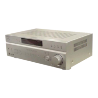
| Dimensions | 43 cm x 15.75 cm x 31.5 cm |
| Dimensions (W x H x D) | 43 cm x 15.75 cm x 31.5 cm |
Information on the characteristics and handling of unleaded solder.
Explanation of the lead-free mark found on components.
Specific instructions for replacing critical IC components on boards.
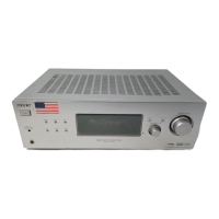
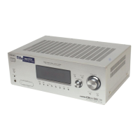
Identification and function of front panel controls and indicators.
Detailed explanation of the various indicators on the display.
Description of all input/output terminals on the rear panel.
Functions and operations of the supplied remote commander.
General sequence for disassembling the unit.
Step-by-step guide for removing the external case.
Instructions for detaching the back panel assembly.
Instructions for detaching the front panel assembly.
Guidance on removing the main internal chassis and board.
Procedures for FL Check, Version Check, Key Check, and DCAC modes.
Procedure for checking FM tuner operation via automatic scanning.
Overview of the main processing and signal flow.
Detailed block diagram of the HDMI interface circuitry.
Block diagram illustrating the Digital Signal Processing functions.
Diagram showing the audio signal paths and processing stages.
Block diagram of the power supply unit and its regulators.
Visual breakdown of front panel parts with references.
Visual breakdown of back panel parts and connectors.
Visual breakdown of main internal chassis and components.
Comprehensive list of all electrical components by board.