EasyManua.ls Logo

Sony STR-V7700 User Manual

Sony STR-V7700
31 pages
To Next Page IconTo Next Page
Page #1 background imageLoading...
Page #1 background image
STR-V7700
E Model
Chinese Model
SERVICE MANUAL
FM STEREO/FM-AM RECEIVER
MICROFILM
STR-V7700 is RECEIVER section in
MHC-V7700AV.
SPECIFICATIONS
Manufactured under license from Dolby Laboratories
Licensing Corporation.
“DOLBY”, “PRO LOGIC” and the double-D symbol a are
trademarks of Dolby Laboratories Licensing Corporation.
— Continued on next page —
Amplifier section
Continuous RMS power output
FRONT SPEAKER:
China model 100+100 watts
6 ohms at 1 kHz, 10%
THD (240V AC supply)
85+85 watts
6 ohms at 1 kHz, 10%
THD (220V AC supply)
Other models 100+100 watts
(6 ohmsat 1 kHz,10%
THD)
CENTER SPEAKER:
45watts (reference)
(8 ohms at 1 kHz, 10%
THD)
REAR SPEAKER:
30+30 watts (reference)
(8 ohms at 1 kHz, 10%
THD)
Peak music power output:
1800 watts (reference)
Inputs MD/VIDEO 1 IN (phono
jacks): voltage 250 mV,
impedance 47 kilo ohms
AV INPUT AUDIO
(phono jacks): voltage 250
mV, impedance 47 kilo
ohms
MIX MIC 1/2 (phone
jack): sensitivity 1 mV,
impedance 10 kilo ohms
Outputs MD/VIDEO 1 OUT
(phono jacks): voltage 250
mV, impedance 1 kilo ohm
PHONES (stereo phone
jack): accepts headphones
of 8 ohms or more.
FRONT SPEAKER:
accepts impedance of 6 to 16
ohms
CENTER SPEAKER:
accepts impedance of 8 to 16
ohms
REAR SPEAKER:
accepts impedance of 8 to 16
ohms
SUPER WOOFER:
Voltage 1 V, impedance 1
kilo ohm
Video section
Inputs AV INPUT VIDEO
(phono jack):
1 Vp-p, 75 ohms
VIDEO IN (phono jack):
1 Vp-p, 75 ohms
Outputs MONITOR OUT (phono
jack): 1 Vp-p, 75 ohms
VIDEO OUT (phono
jack): 1 Vp-p, 75 ohms
S-VIDEO (4-pin/mini-
DIN jack):
Y: 1 Vp-p, unbalanced,
sync negative
C: 0.286 Vp-p, load
impedance 75 ohms
Tuner section
FM stereo, FM/AM superheterodyne tuner
FM tuner section
Tuning range 87.5-108.0 MHz
Antenna terminals 75 ohm unbalanced
Intermediate frequency 10.7 MHz
AM tuner section
Tuning range
Thai models: 531-1,602 kHz
(with the AM tuning
interval set at 9 kHz)
530-1,710 kHz
(with the AM tuning
interval set at 10 kHz)
Other models: MW
531-1,602 kHz
(with the MW tuning
interval set at 9 kHz)
530-1,710 kHz
(with the MW tuning
interval set at 10 kHz)
SW
5.95-17.90 MHz
(with the SW tuning
interval set at 5 kHz)
Intermediate frequency450 kHz
Antenna AM loop antenna
External antenna terminal
Question and Answer IconNeed help?

Do you have a question about the Sony STR-V7700 and is the answer not in the manual?

Sony STR-V7700 Specifications

General IconGeneral
Number of Channels2
Tuning rangeFM, MW
Power Output100 watts per channel into 8Ω (stereo)
Damping factor40
Speaker load impedance8Ω to 16Ω
Dimensions430 x 150 x 380mm (W x H x D)

Summary

Specifications

Amplifier Section Specifications

Details continuous RMS power output and peak music power.

Video Section Specifications

Details video inputs and outputs including impedance and voltage.

Tuner Section Specifications

Details FM and AM tuner section frequency ranges and intermediate frequencies.

General Unit Information

Power and Physical Specifications

Details power requirements, consumption, dimensions, and mass of the unit.

Safety and Component Handling Precautions

Highlights critical safety components and notes for chip component replacement.

Front Panel Controls

Front Panel Button and Jack Identification

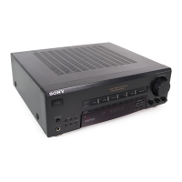
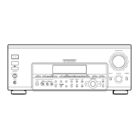
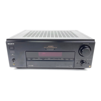
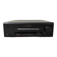
Lists and describes all buttons, jacks, and controls on the front panel.

Back Panel Connections

Rear Panel Terminal and Jack Identification

Lists and describes all terminals and jacks present on the rear panel.

Service Test Modes

FL Display/Key LED Test Mode

Procedure for testing FL segments and LEDs on the display.

General Test Mode (Amplifier/Tuner)

Procedure for testing amplifier and tuner functions.

Aging, Service, and Reset Modes

Covers various modes like aging, service, cold reset, and hot reset.

Circuit Diagrams and Board Layouts

Circuit Board Locations

Diagram illustrating the physical placement of major circuit boards within the unit.

Panel Section Printed Wiring Board

Printed wiring diagram for the panel section with component locations.

Panel Section Schematic Diagram

Schematic diagram for the panel section, including waveform details.

Main Section Printed Wiring Board

Printed wiring diagram for the main section with component locations.

Main Section Schematic Diagram

Schematic diagram for the main section, detailing circuit connections.

Amp/Key Con Section Diagrams

Diagrams for Surround Amp, Amp-A, and Key Con sections.

Mic Echo/AV In Section Diagrams

Diagrams for Mic Echo and AV In sections.

Power Section Diagrams

Diagrams for Supply Power, PRI, and SEC power sections.

Integrated Circuit (IC) Information

IC501 Pin Function (Display Control)

Detailed pinout and function description for IC501 (Display Control).

IC Block Diagrams (LA2786, LV1016)

Block diagrams for IC3001 (LA2786) and IC3000 (LV1016).

Additional IC Pinouts and Diagrams

Pinouts and diagrams for IC105, IC850, IC6002, and IC6003.

Exploded Views and Parts Identification

Main Section Exploded View and Parts

Exploded view diagram and parts list for the main unit section.

Panel Section Exploded View and Parts

Exploded view diagram and parts list for the panel section.

Electrical Parts Lists

AMP-A Board Parts List

Detailed list of electrical components for the AMP-A board.

AVIN, JOG, KEY-CON Board Parts List

List of electrical components for AVIN, JOG, and KEY-CON boards.

KEY-CON MAIN Board Parts List

List of electrical components for the KEY-CON MAIN board.

MAIN Board Parts List

List of electrical components for the MAIN board (Part 1).

MIC ECHO Board Parts List

List of electrical components for the MIC ECHO board.

MIC ECHO, PANEL, VOLUME Board Parts List

List of components for MIC ECHO, PANEL, and VOLUME boards.

PANEL VOLUME Board Parts List

List of electrical components for the PANEL VOLUME board (Part 1).

PRI, SEC, SURROUND AMP Board Parts List

List of components for PRI, SEC, and SURROUND AMP boards.

SUPPLY POWER, SUR Board Parts List

List of electrical components for SUPPLY POWER and SUR boards.

Service Manual Corrections

Correction of Parts List

Details a specific correction to the parts list on page 45.

Related product manuals