2-12(E)
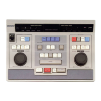
SX-M700
2-3-5.
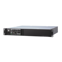
Removal of the HP-65 Board (SX-M700/M100)
Procedure
1. Remove the top panel. (Refer to section, “2-1.
REMOVAL OF THE EXTERNAL PANELS”.)
2. Remove the front panel assembly. (Refer to section, “2-
1. REMOVAL OF THE EXTERNAL PANELS”.)
3. Remove the fixing nut securing the headphone jack.
4. Remove the fixing nut securing the volume control
potentiometer.
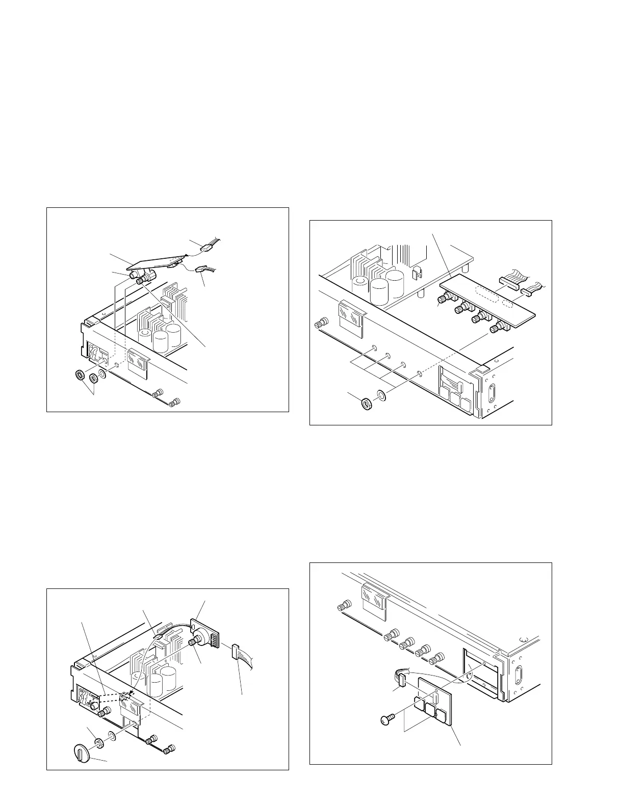
2-3-6.
Removal of the SW-722 Board (SX-M700)
Procedure
1. Remove the top panel. (Refer to section, “2-1.
REMOVAL OF THE EXTERNAL PANELS”.)
2. Remove the front panel assembly. (Refer to section, “2-
1. REMOVAL OF THE EXTERNAL PANELS”.)
3. Remove the selector knob.
4. Disconnect the connector (CN1) from the HP-65 board.
5. Remove the fixing nut securing the volume control
potentiometer.
6.
Disconnect the connector (CN2) from the SW-722 board.
Connector CN1
SX-M700
(from SW-722 board)
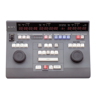
SX-M100
(from AA-93 board)
HP-65
board
Headphone
jack
Connector CN2
(from MT-105 board)
Volume control
potentiometer
Fixing nuts
Connector
CN1
SW-722 board
Volume control
potentiometer
Connector CN2
(from AA-93 board)
Selector knob
Fixing nuts
HP-65 board
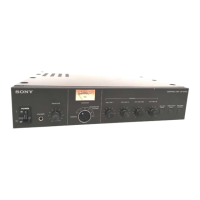
2-3-7.
Removal of the VR-237 Board (SX-M700/M100)
Procedure
1. Remove the top panel. (Refer to section, “2-1.
REMOVAL OF THE EXTERNAL PANELS”.)
2. Remove the front panel assembly. (Refer to section, “2-
1. REMOVAL OF THE EXTERNAL PANELS”.)
3. Remove the four fixing nuts securing the volume
control potentiometers.
4.
Disconnect the connectors (CN1, CN2) from the VR-237
board.
2-3-8.
Removal of the SW-710 Board (SX-M700/M100)
Procedure
1. Remove the front panel assembly. (Refer to section, “2-
1. REMOVAL OF THE EXTERNAL PANELS”.)
2. Disconnect the connector (CN1) from the SW-710
board.
3. Remove the two fixing screws (BVTP 3x8) securing
the SW-710 board.
Volume
control
potentimeter
VR-237 board
Fixing nuts
CN1
CN2
Connector CN1
(from CPU-181 board)
Screws (2 pcs)
BVTP 3x8
SW-710 board
 Loading...