1(E)
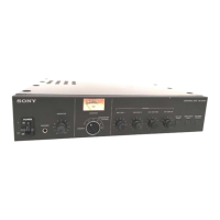
SX-M700
TABLE OF CONTENTS
1. OPERATING INSTRUCTIONS
SX-M700/C700A/C750/D700A/D750/P700/T100....
1-1(E)
SX-M100/C100A/C150/D100A/D150/T100 .........
1-16(E)
2. SERVICE OVERVIEW
2-1. Removal of the external panels ........................ 2-1(E)
2-2. Board Locations ............................................... 2-4(E)
2-3. Board Removal (SX-M700/M100/E120) ......... 2-6(E)
2-3-1. Removal of the PS-364 Board .................. 2-6(E)
2-3-2. Removal of the CPU-181 Board............... 2-8(E)
2-3-3. Removal of the AA-93 Board
(SX-M700/M100)................................... 2-10(E)
2-3-4. Removal of the AL-31 Board
(SX-E120)............................................... 2-11(E)
2-3-5. Removal of the HP-65 Board
(SX-M700/M100)................................... 2-12(E)
2-3-6. Removal of the SW-722 Board
(SX-M700) ............................................. 2-12(E)
2-3-7. Removal of the VR-237 Board
(SX-M700/M100)................................... 2-12(E)
2-3-8. Removal of the SW-710 Board
(SX-M700/M100)................................... 2-12(E)
2-4. Installation of the Expansion Board
(SXA-120) ...................................................... 2-13(E)
2-5. Removal of the Velcro Fastener Tape
(SX-T100) ...................................................... 2-14(E)
2-6. Rack Mount .................................................... 2-15(E)
2-7. Connector Input and Output Signals .............. 2-16(E)
2-8. Switch Setting................................................. 2-18(E)
2-9. Power Cord (Supplied) ................................... 2-18(E)
2-10. Safety Check-Out ........................................... 2-19(E)
3. SYSTEM CONFIGURATION AND
CIRCUIT DESCRIPTION
3-1. System Configuration....................................... 3-1(E)
3-2. Circuit Descriptions.......................................... 3-2(E)
3-2-1. Digital Block ............................................ 3-2(E)
3-2-2. Audio Block.............................................. 3-3(E)
4. TROUBLESHOOTING
4-1. System Diagnostics .......................................... 4-1(E)
4-2. Troubleshooting Procedure ............................. 4-2(E)
4-2-1. If Error-1 Occurs in Connected Units ...... 4-2(E)
4-2-2. If Error-1 to Error-3 Occurs in a
Single Unit................................................ 4-2(E)
4-2-3. Check Points in Case of Error .................. 4-3(E)
(Assuming That the Input and
Output Stages are Normal) ....................... 4-3(E)
4-3. Self Diagnostics of CPU-181 Board ................ 4-4(E)
4-3-1. Checking the CPU .................................... 4-4(E)
4-3-2. Checking the Keys and LEDs................... 4-4(E)
4-3-3. Checking the Lines Connecting
the Delegate and Chairman Units ............. 4-4(E)
4-3-4. Factory Default Settings ........................... 4-4(E)
4-4. Self Diagnostics of CPU-188 Board ................ 4-5(E)
4-4-1. Checking the CPU .................................... 4-5(E)
4-4-2. Checking the SIO ..................................... 4-5(E)
4-4-3. Factory Default Settings ........................... 4-5(E)
4-5. Self Diagnostics of
SX-C700/C100/D700/D100 ............................. 4-6(E)
4-6. SX-T100 Check Items ...................................... 4-6(E)
5. ELECTRICAL ALIGNMENT
5-1. Required Equipment ......................................... 5-1(E)
5-2. Locations of Parts (Side A) .............................. 5-1(E)
5-3. Connecting Diagram......................................... 5-2(E)
5-4. PS-364 Board, Oscillating Frequency
Adjustment ....................................................... 5-2(E)
5-5.
Output Voltage (PS-364 Board) Adjustment .....
5-3(E)
5-6. Output Voltage (PS-364 Board) check ............. 5-3(E)
5-7. VU Meter Adjustment ...................................... 5-4(E)
6.
SEMICONDUCTOR PIN ASSIGNMENTS
.... 6-1
7. REPAIR PARTS
7-1. Notes on Repair Parts ............................................ 7-1
7-2. Exploded Views .................................................... 7-2
7-3. Electrical Parts List ............................................... 7-7