Do you have a question about the Sony TC-KB920S and is the answer not in the manual?
Details harmonic distortion, frequency response, and S/N ratios.
Lists winding times, head types, motors, and input specs.
Covers power requirements, physical size, and included items.
Identifies model codes associated with different market regions.
Offers guidance on soldering and chip component replacement.
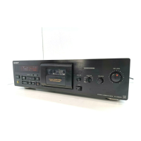
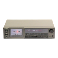
Identifies and explains the function of each control on the front panel.
Details steps for removing the outer case and front panel assembly.
Outlines the procedure for removing the MD assembly.
Describes detaching the main board and cassette holder assembly.
Instructions for fitting base block and head components.
Shows the audio board, capstan motor, and reel motor connections.
Lists precautions and torque specifications for adjustments.
Guides on adjusting record/playback head height and declination.
Procedure for setting the head azimuth for optimal playback.
Defines standard signal levels and test tape usage.
Instructions for adjusting tape speed, playback level, and bias.
Procedures for setting recording input level and equalization.
Explains conventions for schematic and wiring diagrams.
Shows component layouts for Audio and Leaf SW boards.
Circuit diagrams for Audio and Leaf SW boards.
Illustrates waveforms and functional diagrams for main board ICs.
Diagram showing the placement of components on the main board.
Part 1 of the schematic diagram for the main board.
Layout and circuit diagram for the Dolby-S section.
Layouts for power boards and the power section circuit diagram.
Layouts for Panel, Rec Vol, and HP boards.
Circuit diagrams for panel controls, Rec Vol, HP, and Balance.
Detailed pin function descriptions for the main board IC.
Exploded views of the main chassis, case, and front panel assemblies.
Exploded view of individual front panel controls and parts.
Exploded view of the MD mechanism assembly parts.
Detailed exploded view of the MD assembly components.
Exploded view of the first part of the mechanism deck.
Exploded view of the second part of the mechanism deck.
| Track System | 4-track, 2-channel stereo |
|---|---|
| Heads | 3 (Record, Playback, Erase) |
| Motor | DC Servo Motor |
| Noise Reduction | Dolby B, C |
| Outputs | Line Out, Headphone Out |
| Tape Speed | 4.76 cm/s |
| Tape Type | Type I, II, IV |
| Frequency Response | 20Hz to 20kHz (Metal tape) |
| Wow and Flutter | 0.07% (WRMS) |
| Output | Line Out |
| Inputs | Line In, Mic In |
| Dimensions | 430 x 310mm |