EasyManua.ls Logo

Sony TCM-2 - Schematic Diagram

Sony TCM-2
15 pages
Print Icon
To Next Page IconTo Next Page
To Previous Page IconTo Previous Page
Loading...
a
&
4
TCM-2
©
TCM-2
1
2
4
5
6 9
10
11
12
13
14
15
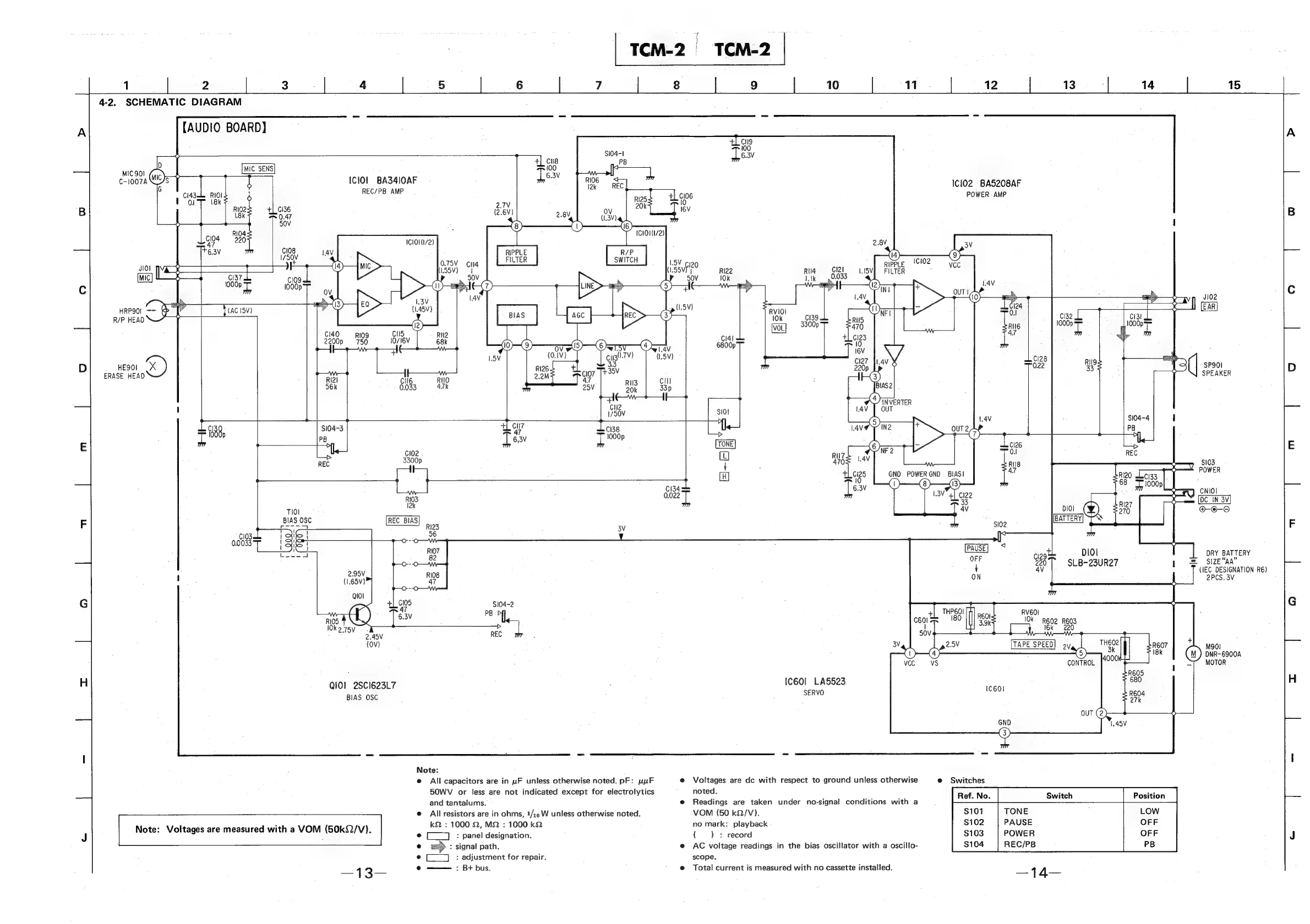
4-2.
SCHEMATIC
DIAGRAM
[AUDIO
BOARD]
+
aL
cue
Si04
TeV
MIC
901
°
Beets
Tesv
I
c-1007AN
5
is
Melo}
Sess
lOne
R06
Icl02
BAS208AF
polo
=
ig
ae
+]
cis
POWER
AMP
;
R102
+[.C136
2
18k
HL
cis
26M)
2.8V
(1.3V)
a3
50V
1
RIO4
Lop
220
Iclo11i72)
2.8V
Treav
C108
+
C102
.
RIPPLE
JIOl
£
(1.55V
RI22
Rig
Cll
FILTER
;
[wi
oe
C199
Ss
Pio
033
|
(ee
J102
HRP9O]
=~
|
}tacisvy
i
'
[EAR]
R/P
HEAD
@
“C140
RIog
ae
cal
2200p
750
STSV
6800p]
a
cu3l:7V)
HEQOI
3.3
pile
(|
SP90I
ERASE
0)
WF
t———-w—
SPEAKER
RI2I
CII6
RIO
RII3
56k
0.033
4.7k
ode
Gl
i
ten
™
S103
+.
POWER
-~
p
CNIOI
As
aap
™
LBV
Clee
SC
IN
SV
av
Diol
(¥)
@-€-9
a
|
REC
BIAS
Rigs
$02
BATTERY.
Vv
56
:
ih
#—O---O
<3
ped
PAUSE
cie9e
DIO!
DRY
BATTERY
nes
oer
22007
SLB-23UR27
&
Size
aA
R108
{
4V
(IEC
DESIGNATION
R6)
pi
ON
2PCS.
3V
e-0---0
+
veg
$104-2
6.3
ea
ee
"80
=
be
ine
R602
REOS
SS
—
=
i
16k
220
REC
TAPE
SPEED
2V
SD
M901
DNR~6900A
CONTROL
MOTOR
QIOl
2SCI623L7
IC60l_
LASS23
BIAS
OSC
SERVO
Note:
e@
All
capacitors
are
in
uF
unless
otherwise
noted.
pF:
yur
e
Voltages
are
dc
with
respect
to
ground
unless
otherwise
@
Switches
50WV
or
less
are
not
indicated
except
for
electrolytics
noted.
Position
and
tantalums.
e@
Readings
are
taken
under
no-signal
conditions
with
a
©
Allresistors
are
in
ohms,
1/19
W
unless
otherwise
noted.
VOM
(50
kQ/V).
TONE
LOW
.
.
kQ
:
1000
2,
MQ
:
1000
k2
no
mark:
playback
PAUSE
OFF
Note:
Voltages
are
measured
with
a
VOM
(50kQ/V).
:
g¢
(
)
©
(__]
:
panel
designation.
()
+
record
POWER
OFF
e
>
:
signal
path.
e@
AC
voltage
readings
in
the
bias
oscillator
with
a
oscillo-
REC/PB
PB
®
(__]
:
adjustment
for
repair.
scope.
e
——-:
B+
bus.
'
@
Total
current
is
measured
with
no
cassette
installed.