EasyManua.ls Logo

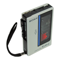
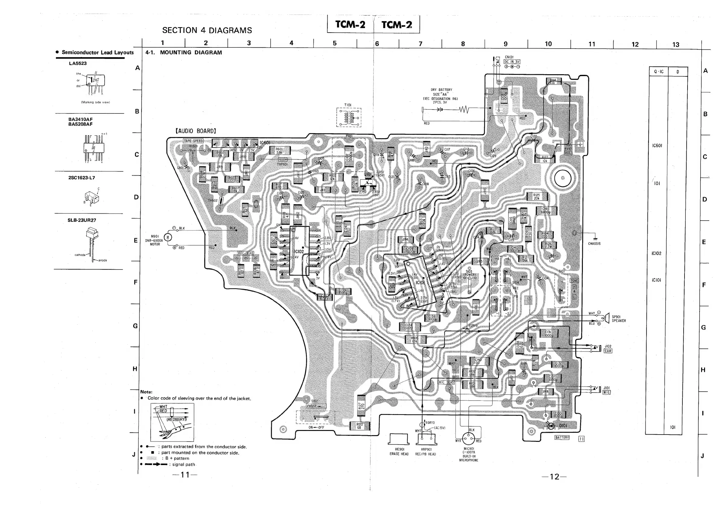
Sony TCM-2 - Mounting Diagram

Sony TCM-2
15 pages
Print Icon
To Next Page IconTo Next Page
To Previous Page IconTo Previous Page
Loading...
SECTION
4
DIAGRAMS
1
2
3
@
Semiconductor
Lead
Layouts
4-1.
MOUNTING
DIAGRAM
LA5523
A
lihe
doi
f
de
n
(Marking
side
view)
B
BA3410AF
BA5208AF
:
ee
{AUDIO
BOARD}
Cc
2SC
1623-L7
D
SLB-23UR27
M901
E
|
pNR-6900a
MOTOR
cathode
anode
F
G
H
Note:
@
Color
code
of
sleeving
over
the
end
of
the
jacket.
l
@
e—
:
parts
extracted
from
the
conductor
side.
J
e
m
:
part
mounted
on
the
conductor
side.
:
B
+
pattern
0
eee
ee:
signal
path
4.
5
6
7
8 9
10
11
12
13
CNIO!
DC
IN
3V
P97?
OO
DRY
BATTERY
size
“AA”
(IEC
DESIGNATION
R6)
2PCS.
3V
CHASSIS
SP901
SPEAKER
Jl02
JIOl
MIC
&
ama,
A
a
eR
=
‘
GRY
Q
(AC
I5V)
a
HE9OI
HRPSOI
MIC9Oi
:
C-1007A
ERASE
HEAD
—REC/PB
HEAD
BUILT-IN
MICROPHONE