EasyManua.ls Logo

Sony TRINITRON KV-29FS150 User Manual

Sony TRINITRON KV-29FS150
85 pages
To Next Page IconTo Next Page
Page #1 background imageLoading...
Page #1 background image
TRINITRON
®
COLOR TELEVISION
SERVICE MANUAL
BX-1L
CHASSIS
MODEL NAME REMOTE COMMANDER DESTINATION CHASSIS NO.
9-883-732-01
KV-29FS150
RM-YA005 LATIN NORTH SCC-S79I-A
KV-29FS150
RM-YA005 LATIN SOUTH SCC-S79J-A
HISTORY INFORMATION FOR THE FOLLOWING MANUAL:
ORIGINAL MANUAL ISSUE DATE: 1/2007
REVISION DATE SUBJECT
1/2007 No revisions or updates are applicable at this time.

Table of Contents

Question and Answer IconNeed help?

Do you have a question about the Sony TRINITRON KV-29FS150 and is the answer not in the manual?
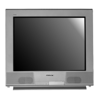
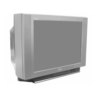
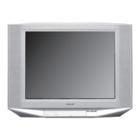
Sony TRINITRON KV-29FS150 Specifications

General IconGeneral
Screen Size29 inches
Display TypeCRT
Resolution480i
Aspect Ratio4:3
Comb Filter3D Digital Comb Filter
Speakers2
InputsComposite, S-Video
Sound Output2 x 10 W

Summary

Section 1: Disassembly

1-1. Rear Cover Removal

Procedure for removing the rear cover.

1-2. Chassis Assembly Removal

Procedure for removing the chassis assembly.

1-3. Service Position

How to position the unit for service.

1-4. Picture Tube Removal

Procedure for removing the picture tube.

Section 2: Set-Up Adjustments

2-1. Beam Landing

Adjusting beam landing for picture quality.

2-2. Convergence

Adjusting color convergence for proper image alignment.

2-3. Focus Adjustment

Adjusting focus for a clear picture.

2-4. Screen (G2)

Adjusting the screen (G2) voltage for brightness.

Section 3: Circuit Adjustments

3-1. Remote Adjustment Buttons and Indicators

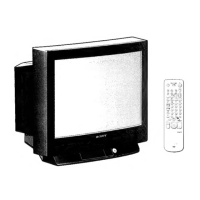
Overview of remote control buttons for adjustments.

3-2. Accessing the Service Menu

Guide to accessing the service menu for adjustments.

3-4. White Balance Adjustments

Procedure for adjusting white balance for accurate colors.

3-5. Picture Quality Adjustments

Adjusting P Max/Contrast for optimal picture.

Section 4: Diagrams

4-1. Circuit Boards Location

Identifies the location of main circuit boards.

4-3. Block Diagram

Visual representation of the TV's signal flow.

4-4. Schematics and Supporting Information

Detailed circuit diagrams for various boards.

4-5. Semiconductors

Identification and diagrams of semiconductor components.

Section 5: Exploded Views

5-1. Chassis

Exploded view and parts list for the chassis assembly.

5-2. Picture Tube

Exploded view and parts list for the picture tube assembly.

Section 6: Electrical Parts List

Related product manuals