– 32 –
KV-PF14DK7/PF14L70/PF14M40/PF14M70
KV-PF14P10/PF14P70/PF14Q70
RM-952
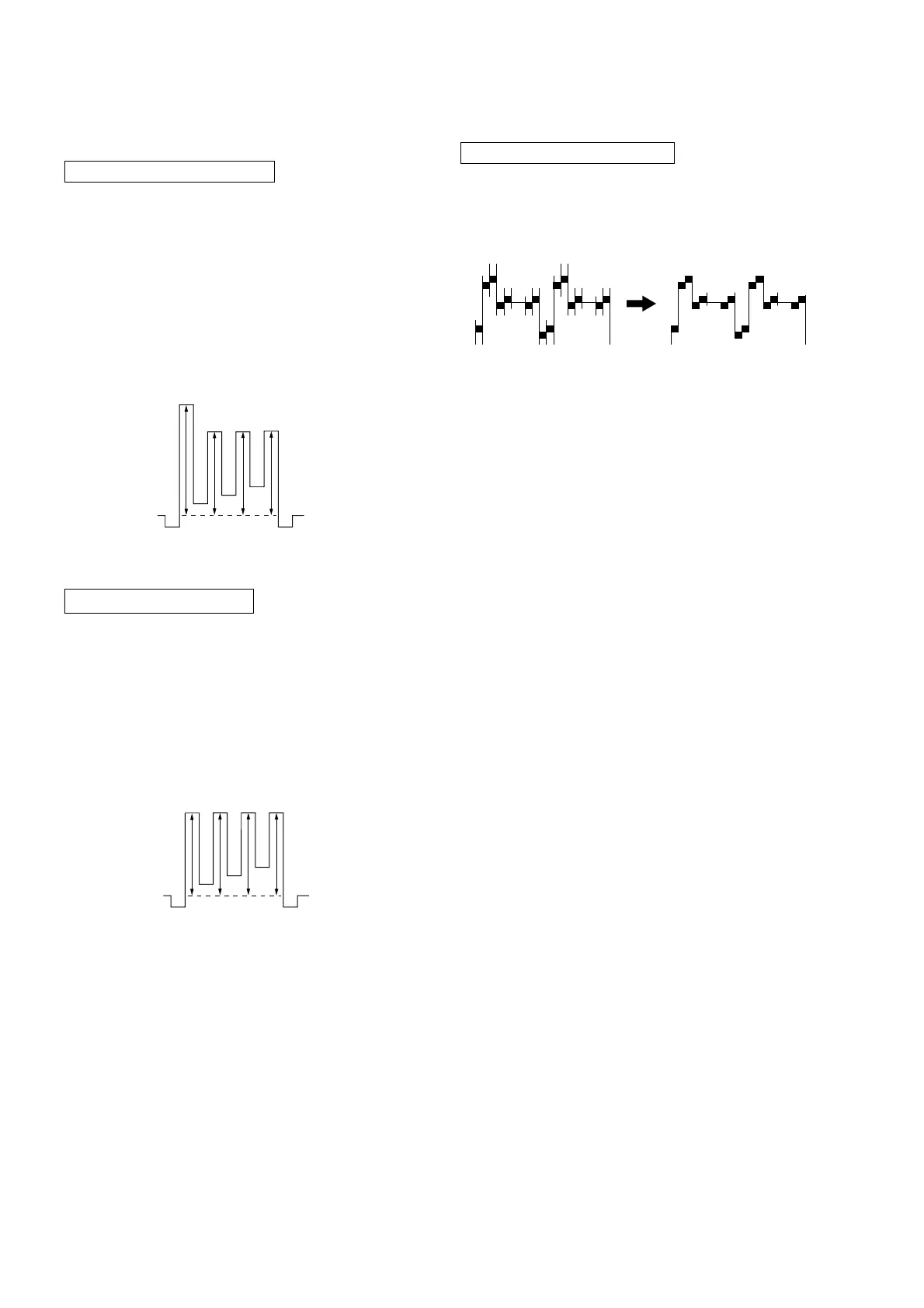
SUB HUE ADJUSTMENT
1. Select Video 1.
2. Input a NTSC color-bar, video into Video 1.
3. Set the following condition:
PICTURE 100%, BRIGHTNESS 50%, COLOR 50%
4. Connect an oscilloscope to pin 1 (B OUT) of CN305, A board.
5. Select SAJ 1 ‘SHU’ with 1 and 4 of the commander by set-
ting to Service Mode and adjust to VB1=VB2=VB3=VB4 with
3 and 6.
4-3. PICTURE QUALITY ADJUSTMENTS
SUB COLOR ADJUSTMENT
1. Input a PAL color-bar.
2. Set to the following condition:
PICTURE 100%, BRIGHTNESS 50%, COLOR 50%
3. Connect an oscilloscope to pin 1 (B OUT) of CN305, A board.
4. Set to Service Mode and select SAJ 3 ‘SCL’ with 1 and 4 of
the commander then adjust to VB2=VB3=VB4 with 3 and
6.
5. Press
[MUTING] → - of the commander to write the data.
6. Adjust SAJ 3 ‘SCL’ as step 2 to 5 when receiving NTSC color-
bar.
VB1 VB2 VB3 VB4
VB2 = VB3 = VB4
6. Press [MUTING] → - of the commander to write the data.
VB1 VB2 VB3 VB4
VB1 = VB2 = VB3 = VB4
BELL FILTER ADJUSTMENT
1. Input SECAM color-bar signal.
2. Connect the dual-trace oscilloscope to the pin 9 (R-Y) of
CN303 (not mounted).
3. Adjust SERVICE MODE, ITEMS ‘SBF’ as shown below.
4-4. A BOARD ADJUSTMENT AFTER IC003
(MEMORY) REPLACEMENT
IC001 (µ-CON): CXP86449-622S (KV-PF14DK7/PF14L70/
PF14M70/PF14Q70 (ME)
CXP86449-623S (except KV-PF14DK7/
PF14L70/PF14M70/PF14Q70 (ME)
1. Enter to Service Mode.
2. Press commander buttons 5 and - (Data Initialize), and 2
and - (Data Copy) to initialize the data.
3. Call each item number and check if the respective screen shows
the normal picture.
In cases where items are not well adjusted, rectify the items
with fine adjustment.
Write the data per each item number (
[MUTING] +-).
4. Select item numbers “OPB0” (OP1), “OPB1” (OP2) and
“OPB2” (OP3) and respectively set the bit per model with
command buttons 3 and 6.
5. Press commander buttons 8 and - (Test Normal) to return
to the data that was set on the shipment from the factory.
(This will also cancel Service Mode.)