EasyManua.ls Logo

Sony TRINITRON KV-SW292M50 User Manual

Sony TRINITRON KV-SW292M50
189 pages
To Next Page IconTo Next Page
Page #1 background imageLoading...
Page #1 background image
REVISION HISTORY
BX1L
MODEL
KV-SW292M50
KV-SW292M50
KV-SW292M61
KV-SW292M80
KV-SW292N60
PART NO.: 9-872-834-02
CHASSIS
NO. SUFFIX DATE SUPP / CORR DESCRIPTION
1 -01 2005/7 _ _ 1st Issue
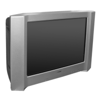
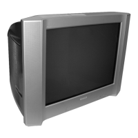
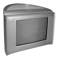
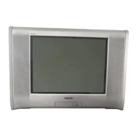
2 -02 2006/2 Corr a) TV Photo incorrect (cover page)
b) Beznet Assy illustration incorrect (page 59)

Table of Contents

Questions and Answers:

Sony TRINITRON KV-SW292M50 Specifications

General IconGeneral
Screen Size29 inches
Display TechnologyCRT
Screen TypeFlat
Audio Output ModeStereo
Remote ControlYes
Aspect Ratio4:3
InputsComposite, RF

Summary

Revision History

Self Diagnostic Function

Diagnostic Test Indicators

Explains how the standby indicator flashes to indicate errors and their causes.

Standby Indicator Blinking Process

Details the timing of the standby indicator blinking.

Standby Indicator on TV Front Panel

Shows the location of the standby indicator on the TV's front panel.

Self Diagnostic Screen Display

Handling Self Diagnostic Screen Display

Provides instructions on how to display, stop, clear, and quit the self-diagnostic screen.

Self-Diagnostic Circuit

Illustrates the circuit diagram related to self-diagnosis.

Section 1 Disassembly

Rear Cover Removal

Details the procedure for removing the rear cover of the TV.

Speaker Removal

Outlines the steps for removing the TV's speaker assembly.

Chassis Assy Removal

Explains how to remove the main chassis assembly from the TV.

Service Position

Describes how to position the TV for service access.

Terminal Bracket Removal

Details the process of removing the terminal bracket.

F2 and J3 Boards Removal

Explains the removal of F2 and J3 boards, noting exceptions.

F1 Board Removal

Outlines the procedure for removing the F1 board.

H4 and H7 Boards Removal

Details the removal of H4 and H7 boards.

A Board Removal

Explains how to remove the A board.

Picture Tube Removal

Provides instructions for safely removing the picture tube.

Section 2 Set-up Adjustments

Beam Landing Adjustment

Details the procedure for adjusting beam landing for picture quality.

Convergence Adjustment

Outlines steps for adjusting color convergence for a sharp picture.

Focus Adjustment

Explains how to adjust the focus for a clear picture.

G2 (SCREEN) Adjustments

Details the adjustment of the G2 (screen) voltage for optimal brightness.

White Balance Adjustment

Covers the procedure for adjusting white balance for accurate colors.

Section 3 Circuit Adjustments

Adjustment with Commander

Explains how to perform service adjustments using the remote commander.

Adjustment Method

Describes the general method for making adjustments via the service menu.

Other Function via Remote Commander

Details additional functions controllable via the remote commander.

Adjustment Item Table

A comprehensive table listing adjustable items, their ranges, and initial values.

Section 4 Diagrams

Block Diagram

Provides a high-level overview of the TV's internal functional blocks.

Circuit Boards Location

Shows the physical location of the main circuit boards within the TV.

Schematic Diagram Information

Explains conventions and symbols used in schematic diagrams.

C Board Schematic Diagram

Detailed schematic for the C board.

A Board — (Block 001)

Schematic for Block 001 of the A board.

A Board — (Block 002)

Schematic for Block 002 of the A board.

A Board — (Block 003)

Schematic for Block 003 of the A board.

J3 Board Schematic Diagram

Schematic for the J3 board.

F1 and H4 Boards Schematic Diagram

Schematics for the F1 and H4 boards.

H7 Board Schematic Diagram

Schematic for the H7 board.

F2 Board Schematic Diagram (except KV-SW292M50 (Thailand))

Schematic for the F2 board, noting exceptions.

VM Board Schematic Diagram

Schematic for the VM board.

Voltage Measurement and Waveform

Provides voltage lists and waveforms for troubleshooting the A board.

4-5. Printed Wiring Boards

H7 Board (Front Panel)

Printed wiring board layout for the H7 board (Front Panel).

J3 Board (DVD Terminal)

Printed wiring board layout for the J3 board (DVD Terminal).

H4 Board (AC Switch)

Printed wiring board layout for the H4 board (AC Switch).

VM Board (Velocity Modulation)

Printed wiring board layout for the VM board (Velocity Modulation).

F2 Board (Rectifier Selection Unit)

Printed wiring board layout for the F2 board (Rectifier Selection Unit).

F1 Board (CISPR)

Printed wiring board layout for the F1 board (CISPR).

4-6. Semiconductors

Section 5 Exploded Views

5-1. Picture Tube and Speaker Bracket

Exploded view showing the assembly of the picture tube and speaker bracket.

5-2. Chassis

Exploded view showing the chassis assembly and related parts.

Section 6 Electrical Parts List

Beznet Assy

Part number and description for the Beznet Assy.

Button, Power

Part number and description for the Power Button.

Picture Tube

Part number and description for the Picture Tube.

Transformer Assy Flyback

Part number and description for the Flyback Transformer Assy.

Tuner, FSS BTP-AG411

Part number and description for the Tuner.

Fuse Holder

Part number and description for the Fuse Holder.

IC Link

Part number and description for the IC Link.

Resistor R001

Resistor R001 specification.

Trinitron Color TV Operating Instructions

Installation

Instructions for securing the TV to prevent falling.

Overview of Controls

Describes the TV's front and rear panels and remote control buttons.

Advanced Operations

Explains how to select picture and sound modes.

Menu Adjustment

Guides users through adjusting TV settings via the menu.

Additional Information

Provides information on connecting optional components and troubleshooting.

Related product manuals