EasyManua.ls Logo

Sony Trinitron KV-SW29M60K User Manual

Sony Trinitron KV-SW29M60K
17 pages
To Next Page IconTo Next Page
Page #1 background imageLoading...
Page #1 background image
MODEL COMMANDER DEST. CHASSIS NO.
CHASSIS
TRINITRON
®
COLOR TV
SERVICE MANUAL
BX1L
MODEL COMMANDER DEST. CHASSIS NO.
KV-SW29M31
RM-W103 Oceania SCC-V03K-A
KV-SW29M50
RM-W104 E SCC-V21E-A
KV-SW29M50
RM-W104 Thailand SCC-V20P-A
KV-SW29M60K
RM-W109 Thailand SCC-V20L-A
KV-SW29M90
RM-W104 Hong Kong SCC-U97N-A
KV-SW29M91
RM-W103 Russia SCC-V13F-A
KV-SW29N90
RM-W150 Taiwan SCC-V05M-A
RM-W104RM-W103
RM-W150
RM-W109
Question and Answer IconNeed help?

Do you have a question about the Sony Trinitron KV-SW29M60K and is the answer not in the manual?

Sony Trinitron KV-SW29M60K Specifications

General IconGeneral
BrandSony
ModelTrinitron KV-SW29M60K
CategoryTV
LanguageEnglish

Summary

Model and Chassis Information

Model List

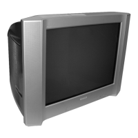
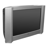
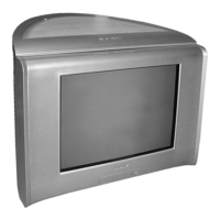
Lists various TV models with their commander and chassis numbers.

Remote Control Identification

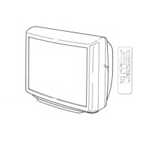
Images of remote controls RM-W103, RM-W104, RM-W109, RM-W150.

Block Diagram Overview

Main Block Diagram

Illustrates the functional blocks of the TV, including tuner, power supply, and audio.

C Board Schematics

RGB Amplifier and Rotation Circuit

Detailed schematic for RGB amplification and rotation control circuits.

H5 Board Schematics

Front Panel Circuitry

Schematic diagram of the H5 board, representing the front panel components and connections.

VM Board Schematics

Velocity Modulation Circuit

Schematic diagram for the VM board, detailing the velocity modulation circuit.

D3 Board Schematics

Dynamic Focus and DQP Circuit

Schematic diagram for the D3 board, covering dynamic focus and DQP functions.

J3 Board Schematics

DVD Terminal Connections

Schematic diagram for the J3 board, detailing DVD terminal connections and protection circuits.

F and H4 Board Schematics

CISPR and Front Panel Circuits

Schematics for the F board (CISPR) and H4 board (Front Panel).

B Board Schematics

AV Switch Circuitry

Schematic diagram for the B board, illustrating the AV switch functionality.

K Board Schematics

Karaoke Circuitry

Schematic diagram for the K board, detailing karaoke function components.

A Board - Block 001 Schematics

Processor, Audio, Tuner, Jack Functions

Schematic detailing processor, audio, tuner, and jack functions on Block 001 of the A board.

A Board - Block 002 Schematics

Power Supply and Deflection Circuits

Schematic detailing power supply and deflection circuits on Block 002 of the A board.

Printed Wiring Boards - A Board

A Board Layout Diagram

Printed wiring board layout for the A board, showing component placement.

Printed Wiring Boards - C, H5, J3

C, H5, and J3 Board Layouts

Printed wiring board layouts for the C, H5, and J3 boards.

Printed Wiring Boards - B, K

B and K Board Layouts

Printed wiring board layouts for the B and K boards.

Printed Wiring Boards - H4, VM

H4 and VM Board Layouts

Printed wiring board layouts for the H4 and VM boards.

Printed Wiring Boards - D3, F

D3 and F Board Layouts

Printed wiring board layouts for the D3 and F boards.

Related product manuals