EasyManua.ls Logo

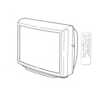
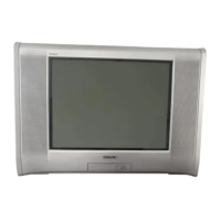
Sony TRINITRON KV-SZ29M80 User Manual

Sony TRINITRON KV-SZ29M80
111 pages
To Next Page IconTo Next Page
Page #1 background imageLoading...
Page #1 background image
REVISION HISTORY
BX1L
MODEL
KV-SZ29M80
KV-SZ29M80
KV-SZ29N60
PART NO.: 9-872-878-01
CHASSIS
NO. SUFFIX DATE SUPP / CORR DESCRIPTION
1 -01 2006/2 _ _ 1st Issue

Table of Contents

Questions and Answers:

Sony TRINITRON KV-SZ29M80 Specifications

General IconGeneral
BrandSony
ModelTRINITRON KV-SZ29M80
CategoryTV
LanguageEnglish

Summary

SELF DIAGNOSTIC FUNCTION

1. DIAGNOSTIC TEST INDICATORS

Interpreting STANDBY indicator flashes for fault diagnosis.

2. STANDBY INDICATOR BLINKING PROCESS

Explains the blinking pattern of the standby indicator.

3. STANDBY INDICATOR ON TV FRONT PANEL

Location of the standby indicator on the TV's front panel.

4. SELF DIAGNOSTIC SCREEN DISPLAY

Displaying diagnostic results on the TV screen.

5. HANDLING SELF DIAGNOSTIC SCREEN DISPLAY

Procedures for displaying and clearing self-diagnostic results.

6. SELF-DIAGNOSTIC CIRCUIT

Schematic of the self-diagnostic circuit and its components.

SECTION 1 DISASSEMBLY

1-1. REAR COVER REMOVAL

Steps to remove the rear cover from the TV.

1-2. SPEAKER REMOVAL

Instructions for removing the speaker assembly.

1-3. CHASSIS ASSY REMOVAL

Procedure for removing the main chassis assembly.

1-4. SERVICE POSITION

Details on placing the TV in a service position.

1-5. H1 BOARD REMOVAL

Steps to remove the H1 board.

1-6. A BOARD REMOVAL

Procedure for removing the A board.

1-7. PICTURE TUBE REMOVAL

Instructions for safely removing the picture tube.

SECTION 2 SET-UP ADJUSTMENTS

2-1. BEAM LANDING ADJUSTMENT

Adjusting beam landing for optimal picture alignment.

2-2. CONVERGENCE ADJUSTMENT

Correcting color convergence for red, green, and blue dots.

2-3. FOCUS ADJUSTMENT

Procedure for adjusting the focus of the picture.

2-4. G2 (SCREEN) ADJUSTMENTS

Adjusting the G2 (screen) voltage for proper brightness.

2-5. WHITE BALANCE ADJUSTMENT

Calibrating white balance for accurate color reproduction.

SECTION 3 CIRCUIT ADJUSTMENTS

3-1. ADJUSTMENT WITH COMMANDER

Performing service adjustments using the remote commander.

3-2. ADJUSTMENT METHOD

General method for performing adjustments via service mode.

3-3. PICTURE QUALITY ADJUSTMENT

Detailed adjustments for picture quality parameters.

3-4. GEOMETRY ADJUSTMENT

Adjusting geometric distortion for correct picture shape.

SECTION 4 DIAGRAMS

4-1. BLOCK DIAGRAM

Overall block diagram of the TV's system architecture.

4-2. CIRCUIT BOARDS LOCATION

Diagram showing the physical location of circuit boards.

4-3. SCHEMATIC DIAGRAM INFORMATION

Key for understanding schematic diagram symbols and notations.

4-4. VOLTAGE MEASUREMENT AND WAVEFORM

Lists voltages and waveforms at various test points.

4-5. PRINTED WIRING BOARDS

Layout diagrams of the printed circuit board traces.

4-6. SEMICONDUCTORS

Identification and diagrams of common semiconductor components.

SECTION 5 EXPLODED VIEWS

5-1. PICTURE TUBE, SPEAKER BRACKET AND CHASSIS

Exploded view of the main TV components and their assembly.

SECTION 6 ELECTRICAL PARTS LIST

CAPACITOR

List of all capacitors used in the circuit with their specifications.

CONNECTOR

List of all connectors with their pin assignments and types.

DIODE

List of diodes with part numbers and descriptions.

IC

List of integrated circuits used in the TV with part numbers.

TRANSISTOR

List of transistors used in the circuit with their part numbers.

RESISTOR

List of resistors with part numbers and specifications.

Related product manuals