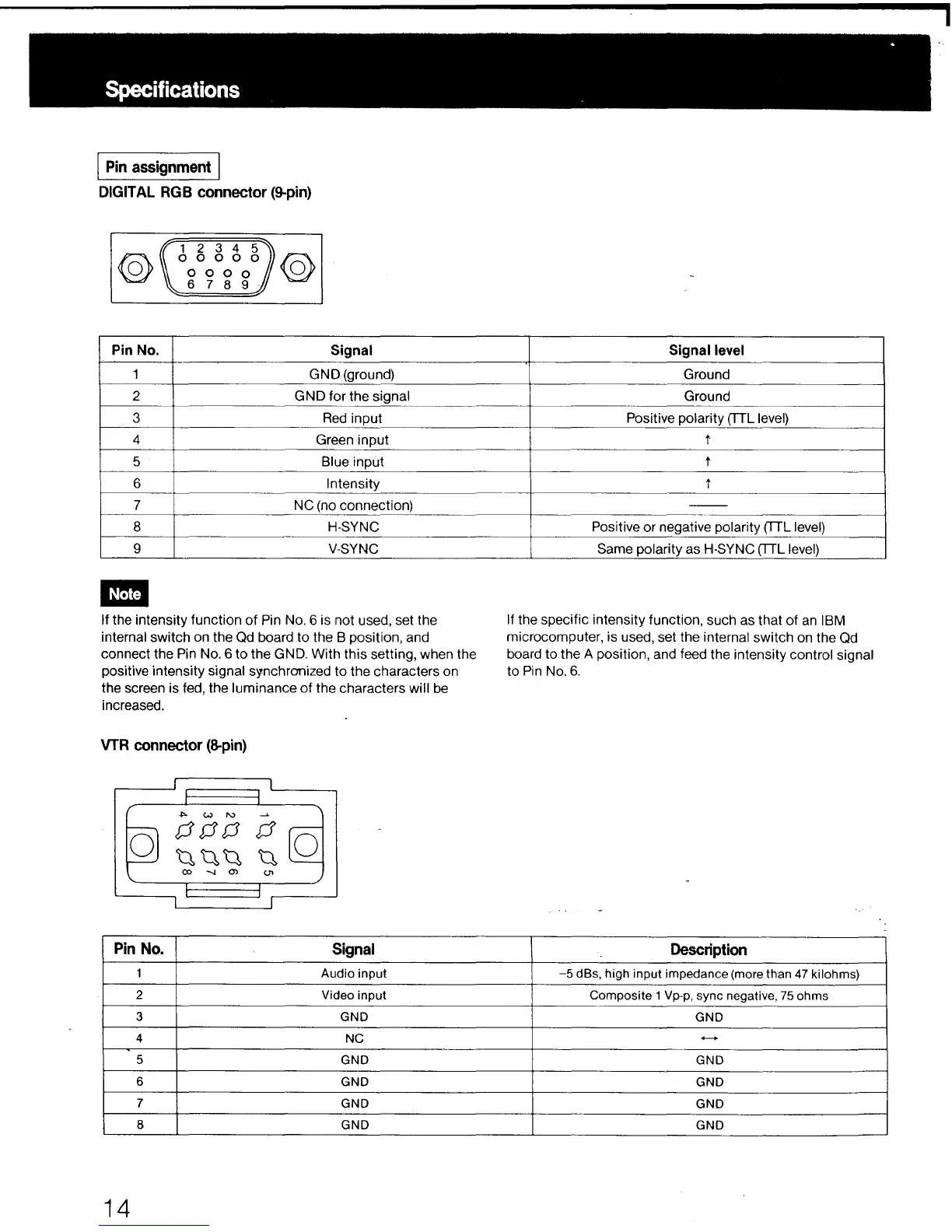
Specifications
j Pin assignment I
DIGITAL RGB connector (9-pin)
@
Pin No.
1
2
3
4
5
6
7
8
g
-
1 2 3 4 5
0 0 0 0 0
0 0 0 0
6 7 8 9
@
Signal
GNO (ground)
GND for the signal
Red input
Green input
Blue input
Intensity
NC (no connection)
H-SYNC
V-SYNC
If the intensity function of Pin No. 6 is not used, set the
internal switch on the Qd board to the B position, and
connect the Pin No. 6 to the GND. With this setting, when the
positive intensity signal synchronized to the characters on
the screen is fed, the luminance of the characters will be
increased.
VTR connector (8-pin)
0
0
Pin No.
Signal
1
Audio input
2
Video input
3
GND
4
NC
5
GND
6
GND
7
GND
8
GND
14
Signal level
Ground
Ground
Positive polarity (TTL level)
t
t
t
--
Positive or negative polarity (TTL level)
Same polarity as H-SYNC (TTL level)
If the specific intensity function, such as that of an IBM
microcomputer, is used, set the internal switch on the Qd
board to the A position, and feed the intensity control signal
to Pin No. 6.
Description
-5 dBs, high input impedance (more than 47 kilohms)
Composite 1 Vp-p, sync negative, 75 ohms
GND
.........
GND
GND
GND
GND
.