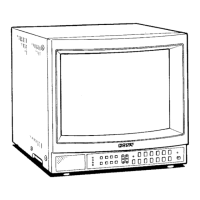
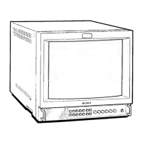
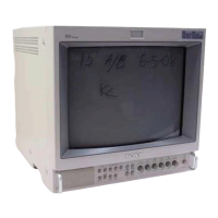
PVM-1353MD/1453MD
R-Y, B-Y channels
Y channel
EXT SYNC IN
Outputs
Y/C OUT
0.7 Vp-p ±6 dB
1.0 Vp-p±6dB
(Standard color bar signal of 75%
chrominance)
BNC connector composite sync
4 Vp-p ±6 dB, negative
4-pin mini DIN connector. 75 ohms
terminated
VIDEO OUT BNC
connector. 75 ohms terminated
AUDIO OUT phono jack
R/R-Y OUT. G/Y OUT.
BIB- Y OUT
EXT SYNC OUT
DC OUT
Speaker output
Remote input
REMOTE
I
RS-232C
General
BNC connector, 75 ohms terminated
BNC connector, 75 ohms terminated
5 V/1 A
Output level 0.8 W
8-pin mini DIN
See
the pin assig11111c111 011 1hc
page 2.
9-pin D-sub
See the pin
assignment 011 the
page 2.
Power requirements 120 V AC. 50/60 Hz
1.3A
Capable of JOO to 240V operation
Operating temperature range
0-35°C
Storage temperature range
-I0-+40°C
Humidity
O - 90%
Dimensions Approx. 346 x 340 x 411.5 mm
(w/h/d)
Mass
(13
5
/8 x 13
1
/2 x 16
1
/4 inches)
not incl. projecting
pans and controls
Approx. 16.7 kg (36 lb 14 oz)
Accessory supplied AC power cord
(I)
0 dBu = 0.775 Vr.111.s.
AC plug holder (I)
Splash proof covers (2)
Control panel cover (I)
Panel hinges (2)
Remote Control Connector
8-pin mini DIN (I)
Operating Instructions ( I)
Interface Manual for Programmers (I)
Quick Reference Card (I)
Double-sided adhesive tapes (4)
Design and specifications are subject to change without
notice.
Pin assignment
V/C IN connector (4-pin mini DIN)
Pin No. Signal
Description
1 Y-input
1 Vp-p, sync negative,
75 ohms
2
CHROMA sub-
300 mVp-p, burst
carrier-input
Delay time between Y and C:
within 0±100 nsec., 75 ohms
3
GND for Y-input GND
4 GND for
GND
CHROMA-input
REMOTE 1 connector (8-pin mini DIN)
Pin No. Signal
1 REMOTE ON/OFF
2
LINEA
3 GND
4
LINE B
5 TALLY
6
OVER SCAN
7 RGBA
8 RGBB
RS-232C connector (9-pin D-sub)
Pin No.
1
2
3
4
5
6
7
8
9
-2-
Signal
-
RX
TX
-
GND
-
RTS
CTS
-
@@@®G)
®@CD@
 Loading...