– 7 –
SECTION 4
ADJUSTMENTS
4-1. MECHANICAL ADJUSTMENTS
PRECAUTION
1. Clean the following parts with a denatured-alcohol-moistened
swab :
record/playback head pinch roller
erase head rubber belts
capstan
2. Demagnetize the record/playback head with a head demagne-
tizer.
3. Do not use a magnetized screwdriver for the adjustments.
4. After the adjustments, apply suitable locking compound to the
parts adjusted.
5. The adjustments should be performed with the rated power sup-
ply voltage unless otherwise noted.
r
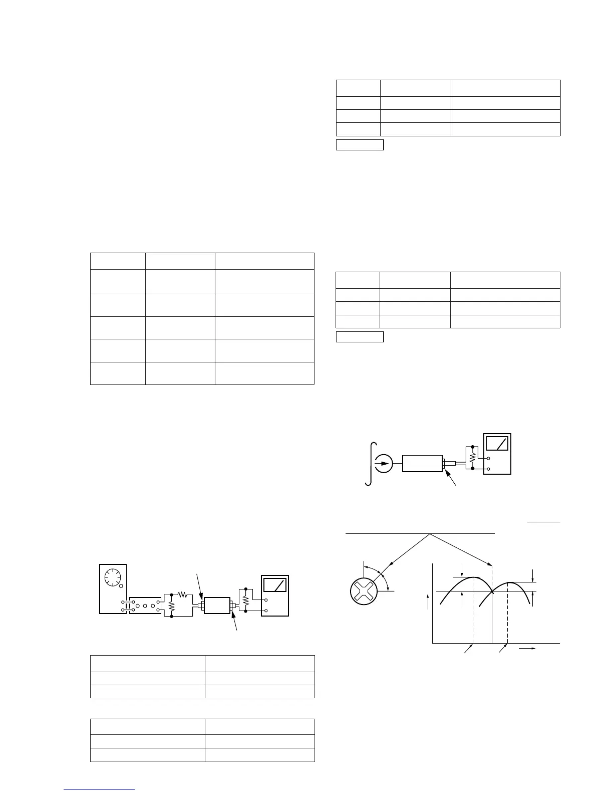
Torque Measurement
Mode Torque Meter Meter Reading
Forward CQ-102C
30 to 65 g•cm
(0.42 – 0.9 oz•inch)
Forward CQ-102C 1 to 7 g•cm
Back Tension (0.0134– 0.097 oz•inch)
Reverse CQ-102RC
30 to 65 g•cm
(0.41 – 0.9 oz•inch)
Reverse CQ-102RC
1 to 7 g•cm
Back Tension
(0.0134– 0.097 oz•inch)
FF, REW CQ-201B
70 to 120 g•cm
(0.972– 1.66 oz•inch)
4-2. ELECTRICAL ADJUSTMENTS
1. The adjustment should be performed in the publication.
(Be sure to make playback adjustment at first.)
2. The adjustment and measurement should be performed for
both L-CH and R-CH.
r
Switch position
DOLBY NR switch : OFF
DIR MODE switch :A
r
Standard record position :
Deliver the standard input signal level to input jack and set
the REC LEVEL control to obtain the standard output signal
level as follows.
Record Mode
set
TAPE OUT
+
–
TAPE IN
AF OSC
attenuator
600
Ω
10 k
Ω
47 k
Ω
level meter
r
Standard Input Level
Input Terminal TAPE IN
source impedance 10kΩ
input signal level 0.5V (–3.8dB)
r
Standard Output Level
Output Terminal TAPE OUT
load impedance 47kΩ
output signal level 0.5V (–3.8dB)
r
Test tape
Tape Contents Use
P-4-A100 10 kHz, –10dB Azimuth Adjustment
P-4-L300 315Hz, 0dB PB Level Adjustment
WS-48B 3kHz, 0dB Tape Speed Adjustment
0dB=0.775V
TC Test Mode
setting : Push POWER button with STOP key and REC MUTE
key.
function :
r
when start recording, COUNTER is set to “0000”
and COUNTER MEMORY function is effective
(“MEMORY” appears on FLD).
r
While playing or AMS, the signal level is displayed.
(“L” / “H”)
r
Test tape
Tape Contents Use
P-4-A100 10 kHz, –10dB Head Azimuth Adjustment
P-4-L300 315Hz, 0dB Level Adjustment
WS-48B 3kHz, 0dB Tape Speed Adjustment
0dB=0.775V
Record/Playback Head Azimuth Adjustment
r
Carrey out servicing or repairs form the REVERSE direction
first.
Procedure :
1. Mode : Forward playback
set
level mete